336,961
REGULATOR FOR DYNAMO-ELECTRIC MACHINES - May 18, 1885
UNITED STATES PATENT OFFICE
NIKOLA TESLA, OF SMILJAN LIKA, AUSTRIA-HUNGARY, ASSIGNOR TO THE TESLA ELECTRIC LIGHT AND MANUFACTURING COMPANY, OF RAHWAY, NEW JERSEY
Nikola Tesla Patent 336,961 REGULATOR FOR DYNAMO-ELECTRIC MACHINES
SPECIFICATION forming part of Letters Patent No. 336,961, dated March 2, 1886
Application filed May 18, 1885. Serial No. 165,793. (No model.)
To all whom it may concern:
Be it known that I, NIKOLA TESLA, of Smiljan Lika, border country of Austria-Hungary, have invented an Improvement in Dynamo Electric Machines, of which the following is a specification.
The object of my invention is to provide an improved method for regulating the current on dynamo-electric machines.
In my improvement I make use of two main brushes, to which the ends of the helices of the field-magnets are connected, and an auxiliary-brush and a branch or shunt-connection to form an intermediate point of the field-wire to the auxiliary-brush.
The relative positions of the respective brushes are varied, either automatically or by hand, so that the shunt becomes inoperative when the auxiliary-brush has a certain position upon the commutator, but when said auxiliary brush is moved in its relation to the main brushes, or the latter are moved in their relation to the auxiliary brush, the electric condition is disturbed and more or less of the current through the field-helices is diverted through the shunt or a current passed over said shunt to the field-helices.
By varying the relative position upon the commutator of the respective brushes automatically in proportion to the varying electrical conditions of the working-circuit the current developed can be regulated in proportion to the demands in the working-circuit.
Devices for automatically moving the brushes in dynamo-electric machines are well known, and those made use of in my machine may be of any desired or known character.
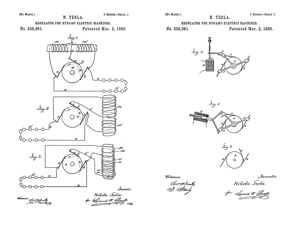
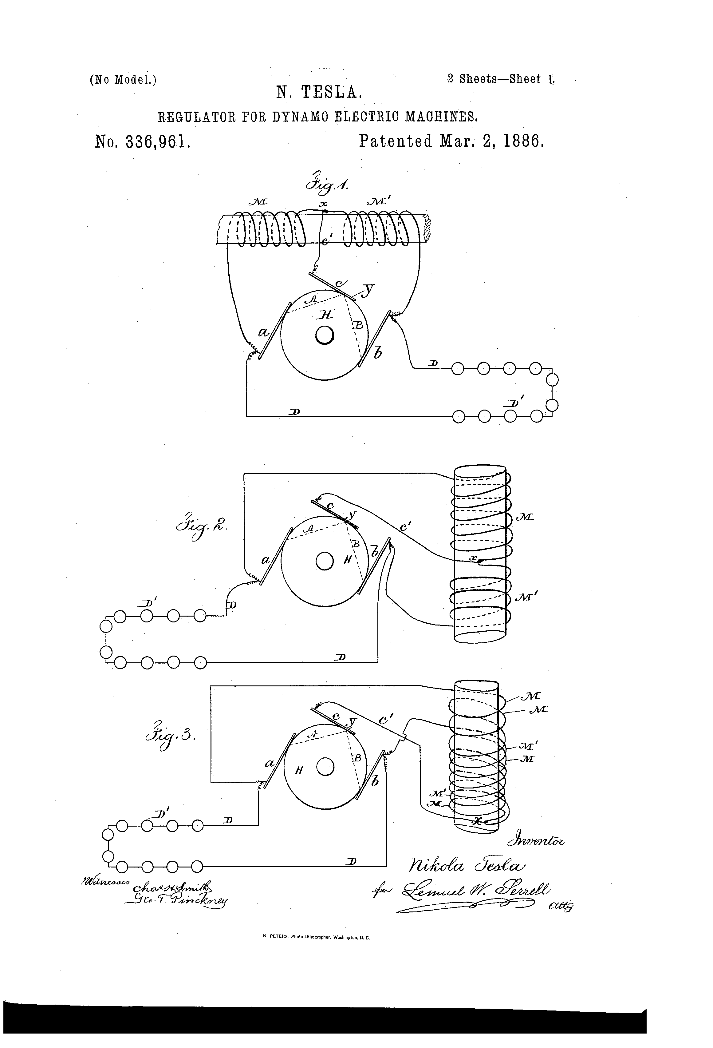
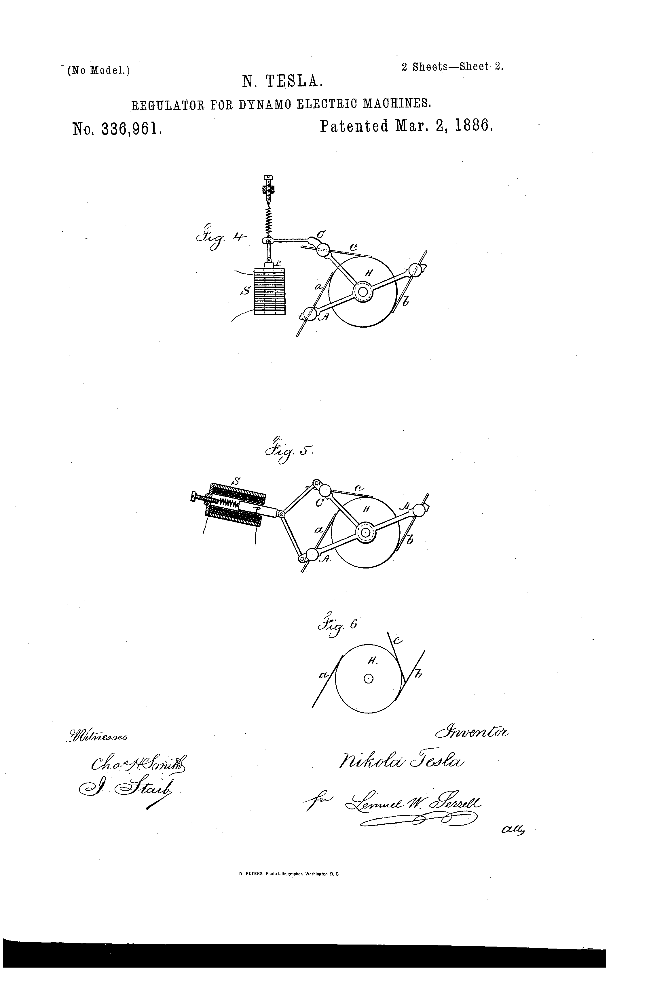
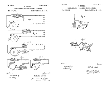
In the drawings, Figure 1 is a diagram illustrating my invention, showing one core of the field-magnets with one helix wound in the same direction throughout. Figs. 2 and 3 are diagrams showing one core of the field-magnets with a portion of the helices wound in opposite directions. Figs. 4 and 5 are diagrams illustrating the electric devices that may be employed for automatically adjusting the brushes, and Fig. 6 is a diagram illustrating the positions of the brushes when the machine is being energized on the start.
a and b are the positive and negative brushes of the main or working-circuit, and c the auxiliary-brush. The working-circuit D extends from the brushes a and b, as usual, and contains electric lamps or other devices, D', either in series or in multiple arc.
M M' represent the field-helices, the ends of which are connected to the main-brushes a and b. The branch or shunt-wire c' extends from the auxiliary-brush c to the circuit of the field-helices, and is connected to the same at an intermediate point, X.
H represents the commutator, with the plates of ordinary construction. It is now to be understood that when the auxiliary brush c occupies such a position upon the commutator that the electric-motive force between the brushes a and c is to the electro-motive force between the brushes c and b as the resistance of the circuit a M c' c A to the resistance of the circuit b M' c' c B, the potentials of the points X and Y will be equal, and no current will flow over the auxiliary brush; but when the brush c occupies a different position the potentials of the points X and Y will be different, and a current will flow over the auxiliary brush to or from the commutator, according to the relative position of the brushes. If, for instance, the commutator-space between the brushes a and c, when the latter is at the neutral point, is diminished, a current will flow from the point Y over the shunt C to the brush b, thus strengthening the current in the part M', and partly neutralizing the current in the part M; but if the space between the brushes a and c is increased, the current will flow over the auxiliary brush in an opposite direction, and the current in M will be strengthened, and in M' partly neutralized.
By combining with the brushes a, b and c any known automatic regulating mechanism the current developed can be regulated in proportion to the demands in the working-circuit. The parts M and M' of the field-wire may be wound in the same direction, (In this case they are arranged as shown in Fig. 1; or, the part M may be wound in the opposite direction, as shown in Figs. 2 and 3.)
It will be apparent that the respective cores of the field-magnets are subject to the neutralizing or intensifying effects of the current in the shunt through c', and the magnetism of the cores will be partially neutralized or the point of greatest magnetism shifted, so that it will be more or less remote from or approaching to the armature, and hence the aggregate energizing actions of the field magnets on the armature will be correspondingly varied.
In the form indicated in Fig. 1 the regulation is effected by shifting the point of greatest magnetism, and in Figs. 2 and 3 the same effect is produced by the action of the current in the shunt passing through the neutralizing-helix.
The relative positions of the respective brushes may be varied by moving the auxiliary brush or the brush c may remain quiescent and the core p be connected to the main brush holder A', so as to adjust the brushes a b in their relation to the brush c. If, however, an adjustment is applied to all the brushes, as seen in Fig. 5, the solenoid should be connected to both A and C, so as to move them toward or away from each other.
There are several known devices for giving motion in proportion to an electric current. I have shown the moving cores in Figs. 4 and 5 as convenient devices for obtaining the required extent of motion with very slight changes in the current passing through the helices. It is understood that the adjustment of the main-brushes causes variations in the strength of the current independently of the relative position of said brushes to the auxiliary brush. In all cases the adjustment may be such that no current flows over the auxiliary brush when the dynamo is running with its normal load.
In Figs, 4 and 5, A A indicate the main brush holder, carrying the main brushes, and C the auxiliary brush holder, carrying the auxiliary brush. These brush holders are movable in arcs concentric with the center of the commutator shaft. An iron piston, P, of the solenoid S, Fig. 4, is attached to the auxiliary brush holder C. The adjustment is effected by means of a spring and screw or tightener.
In Fig. 5, instead of a solenoid, an iron tube enclosing a coil is shown. The piston of the coil is attached to both brush holders A A and C. When the brushes are moved directly by electrical devices, as shown in Figs. 4 and 5, these are so constructed that the force exerted for adjusting is practically uniform through the whole length of motion.
I am aware that auxiliary brushes have been used in connection with the helices of the field-wire; but in these instance the helices received the entire current through the auxiliary brush or brushes, and said brushes could not be taken off without breaking the circuit through the field. These brushes caused, however, a great sparking upon the commutator. In my improvement the auxiliary brush causes very little or no sparking, and can be taken off without breaking the circuit through the field-helices.
My improvement has, besides, the advantages to facilitate the self-exciting of the machine in all cases where the resistance of the field-wire is very great comparatively to the resistance of the main circuit at the start—for instance, on arc-light machines. In this case I place the auxiliary brush c near to or in preference in contact with the brush b, as shown in Fig. 6, In this manner the part M' is completely cut out, and as the part M has a considerably smaller resistance than the whole length of the field-wire the machine excites itself, whereupon the auxiliary brush is shifted automatically to its normal position.
I claim as my invention—
The combination, with the commutator having two or more main brushes and an auxiliary brush, of the field-helices having their ends connected to the main brushes, and a branch or shunt connection from an intermediate point of the field-helices to the auxiliary brush, and means for varying the relative position upon the commutator of the respective brushes, substantially as set forth.
Signed by me this 13th day of May, A.D. 1885
NIKOLA TESLA
Click images for higher-resolution
Source File: US Patent 336,961 - pdf
Chapter XXXVIII - The Martin Book
Auxiliary Brush Regulation of Direct Current Dynamos
Thomas Commerford Martin
An interesting method devised by Mr. Tesla for the regulation of direct current dynamos, is that which has come to be known as the "third brush" method. In machines of this type, devised by him as far back as 1885, he makes use of two main brushes to which the ends of the field magnet coils are connected, an auxiliary brush, and a branch or shunt connection from an intermediate point of the field wire to the auxiliary brush.
The relative positions of the respective brushes are varied, either automatically or by hand, so that the shunt becomes inoperative when the auxiliary brush has a certain position upon the commutator; but when the auxiliary brush is moved in its relation to the main brushes, or the latter are moved in their relation to the auxiliary brush, the electric condition is disturbed and more or less of the current through the field-helices is diverted through the shunt or a current is passed over the shunt to the field-helices. By varying the relative position upon the commutator of the respective brushes automatically in proportion to the varying electrical conditions of the working-circuit, the current developed can be regulated in proportion to the demands in the working-circuit.
Fig. 253 is a diagram illustrating the invention, showing one core of the field-magnets with one helix wound in the same direction throughout. Figs. 254 and 255 are diagrams showing one core of the field-magnets with a portion of the helices wound in opposite directions. Figs. 256 and 257 are diagrams illustrating the electric devices that may be employed for automatically adjusting the brushes, and Fig. 258 is a diagram illustrating the positions of the brushes when the machine is being energized at the start.
a and b are the positive and negative brushes of the main or working-circuit, and c the auxiliary brush. The working-circuit D extends from the brushes a and b, as usual, and contains electric lamps or other devices, D', either in series or in multiple arc.
M M' represent the field-helices, the ends of which are connected to the main brushes a and b. The branch or shunt wire c' extends from the auxiliary brush c to the circuit of the field-helices, and is connected to the same at an intermediate point, x.
H represents the commutator, with the plates of ordinary construction. When the auxiliary brush c occupies such a position upon the commutator that the electro-motive force between the brushes a and c is to the electro-motive force between the brushes c and b as the resistance of the circuit a M c' c A is to the resistance of the circuit b M' c' c B, the potentials of the points x and Y will be equal, and no current will flow over the auxiliary brush; but when the brush c occupies a different position the potentials of the points x and Y will be different, and a current will flow over the auxiliary brush to and from the commutator, according to the relative position of the brushes. If, for instance, the commutator-space between the brushes a and c, when the latter is at the neutral point, is diminished, a current will flow from the point Y over the shunt c to the brush b, thus strengthening the current in the part M', and partly neutralizing the current in part M; but if the space between the brushes a and c is increased, the curent will flow over the auxiliary brush in an opposite direction, and the current in M will be strengthened, and in M', partly neutralized.
By combining with the brushes a, b, and c any usual automatic regulating mechanism, the current developed can be regulated in proportion to the demands in the working circuit. The parts M and M' of the field wire may be wound in the same direction. In this case they are arranged as shown in Fig. 253; or the part M may be wound in the opposite direction, as shown in Figs. 254 and 255.
It will be apparent that the respective cores of the field-magnets are subjected to neutralizing or intensifying effects of the current in the shunt through c', and the magnetism of the cores will be partially neutralized, or the points of greatest magnetism shifted, so that it will be more or less remote from or approaching to the armature, and hence the aggregate energizing actions of the field magnets on the armature will be correspondingly varied.
In the form indicated in Fig. 253 the regulation is effected by shifting the point of greatest magnetism, and in Figs. 254 and 255 the same effect is produced by the action of the current in the shunt passing through the neutralizing helix.
The relative positions of the respective brushes may be varied by moving the auxiliary brush, or the brush c may remain stationary and the core P be connected to the main-brush holder A, so as to adjust the brushes a b in their relation to the brush c. If, however, an adjustment is applied to all the brushes, as seen in Fig. 257, the solenoid should be connected to both a and c, so as to move them toward or away from each other.
There are several known devices for giving motion in proportion to an electric current. In Figs. 256 and 257 the moving cores are shown as convenient devices for obtaining the required extent of motion with very slight changes in the current passing through the helices. It is understood that the adjustment of the main brushes causes variations in the strength of the current independently of the relative position of those brushes to the auxiliary brush. In all cases the adjustment should be such that no current flows over the auxiliary brush when the dynamo is running with its normal load.
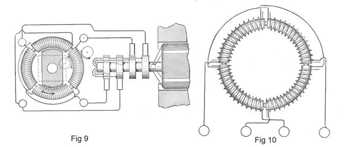
In Figs. 256 and 257 A A indicate the main-brush holder, carrying the main brushes, and C the auxiliary-brush holder, carrying the auxiliary brush. These brush-holders are movable in arcs concentric with the centre of the commutator-shaft. An iron piston, P, of the solenoid S, Fig. 256, is attached to the auxiliary-brush holder C. The adjustment is effected by means of a spring and screw or tightener.
In Fig. 257 instead of a solenoid, an iron tube inclosing a coil is shown. The piston of the coil is attached to both brush-holders A A and C. When the brushes are moved directly by electrical devices, as shown in Figs. 256 and 257, these are so constructed that the force exerted for adjusting is practically uniform through the whole length of motion.
It is true that auxiliary brushes have been used in connection with the helices of the field-wire; but in these instances the helices receive the entire current through the auxiliary brush or brushes, and these brushes could not be taken off without breaking the circuit through the field. These brushes cause, moreover, heavy sparking at the commutator. In the present case the auxiliary brush causes very little or no sparking, and can be taken off without breaking the circuit through the field-helices. The arrangement has, besides, the advantage of facilitating the self-excitation of the machine in all cases where the resistance of the field-wire is very great comparatively to the resistance of the main circuit at the start—for instance, on arc-light machines. In this case the auxiliary brush c is placed near to, or better still in contact with, the brush b, as shown in Fig. 258. In this manner the part M' is completely cut out, and as the part M has a considerably smaller resistance than the whole length of the field-wire the machine excites itself, whereupon the auxiliary brush is shifted automatically to its normal position.
In a further method devised by Mr. Tesla, one or more auxiliary brushes are employed, by means of which a portion or the whole of the field coils is shunted. According to the relative position upon the commutator of the respective brushes more or less current is caused to pass through the helices of the field, and the current developed by the machine can be varied at will by varying the relative positions of the brushes.
Previous Chapter --- Contents --- Next Chapter
Related Patent
336,962
Regulator for Dynamo-Electric Machines - June 1, 1885
Tesla's Arc-Light Technology
Automatic Lamps, Commutators, Regulators, DC Generator or "Dynamo"
To the Archive Page Discussion on Tesla's Technology

Lab-Tesla disclosures on the technology just presented
A NEW SYSTEM OF ALTERNATE CURRENT MOTORS AND TRANSFORMERS
Paper by Nikola Tesla read to the American Institute of Electrical Engineers on May 16, 1888
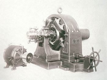
Tesla's Laboratory Power