The Tesla Rotating Magnetic Field
Click Here for higher resolution
Motors with Closed Conductors
Synchronizing Motors
Rotating Field Transformers
Paper by Nikola Tesla read before the American Institute of Electrical Engineers on May 16, 1888
Chapter III - The Martin Book
Preface
This lecture is part of the Lab-Tesla Commentary on Tesla Technology and Wireless. Please see the Archive Page for the first section of commentary. You can click here to skip straight to the paper.
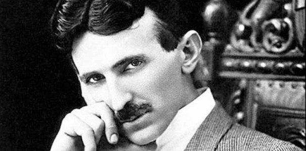
The best documentation of Tesla's early work, and indeed the largest single body of documentation we have today from this period came to us through the efforts of Thomas Commerford Martin. Martin well realized in the years 1888-91 that Tesla was making history. Martin was a personal witness to many demonstrations in Tesla's laboratory at 33 and 35 South Fifth Avenue, he witnessed demonstrations performed by Tesla at the Columbian Exposition - Chicago World's Fair in 1893... Including demonstrations of wireless power transmission and Tesla's wireless motor technology. With Tesla's permission Martin put together a book documenting Tesla's basic work up until 1893, ending with a description of Tesla's exhibits at the World's Fair (link above) and a very short section on mechanical and electrical oscillators.
"The Inventions, Researches, and Writings of Nikola Tesla", known here simply as "The Martin Book", is required reading for any student of Tesla. Where does the Martin book begin? Tesla's alternating current motors, and a revolutionary series of patents that cover the production and exploitation of the rotating magnetic field. The journey begins with a simple two-phase motor/generator set, and never stops.
Martin begins with alternating currents and the rotating magnetic field even though Tesla's patent record had started earlier with the development of direct current arc-light systems. Most students of Tesla start learning/building with resonating spark producing coils, the famous "Tesla Coil", and Tesla himself demonstrated and photographed sparking coils because sparks are demonstrative of power levels being developed: they are easily seen, and heard, in lecture halls and are easily photographed in the laboratory. Sparks also demonstrate the physical geometry of magnetic tubes. But the true magic of Tesla was the way he matched a useful application to a power supply: a process he started by matching the brushless induction motor to his first commerically viable two-phase alternating current generator.
A - Tesla's Egg of Columbus at the 1893 Chicago World's Fair - Columbian Exposition
One of the most useful applications that Tesla had for his two-phase motor-generator technology was never commercially produced, it was a bench-top demonstration device known as "Tesla's Egg of Columbus". Prior to patenting his first alternating current motor/generator set, Tesla hand built a small "Egg of Columbus" which was demonstrated to potential investors who then supplied the capital to pay for the patent applications. Even back then, patent applications were a time consuming, tedious, and expensive proposition.
Once Tesla secured patents that covered the two-phase Egg of Columbus and development of the "modern" polyphase system, the package of patents that makes up our current power grid were sold to Westinghouse for industrial development and implementation. Tesla went to work at Westinghouse, in Pittsburgh, for one year as a consultant and made many friends among the Westinghouse staff. During this period he co-filed on an industrial patent with Albert Schmid, 417,794 - Armature for Electric Machines - Schmid-Tesla - June 28, 1889.
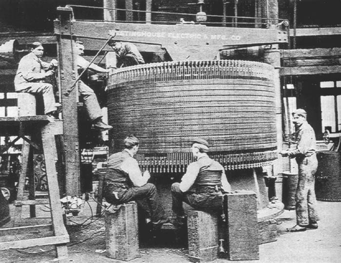
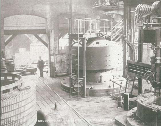
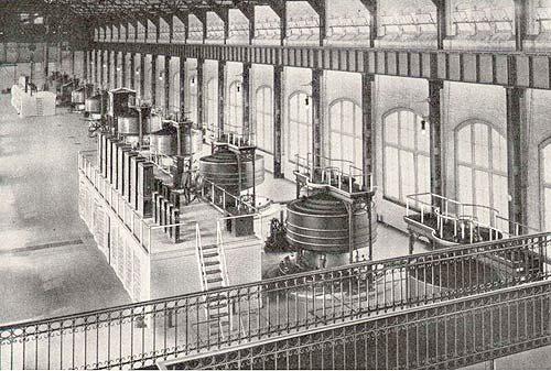
Above: Tesla designed generator armature being wound by Westinghouse employees working on the floor of the future Niagara Falls power plant. Once they were wound, the armatures were mounted in place and then the generators were constructed around them. This armature design was developed from the armature shown and described in Fig 298 and Fig 305 of Tesla's Exhibit at the World's Fair
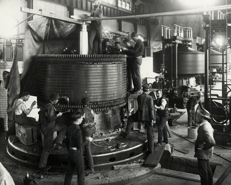
Above: A Tesla generator armature has been mounted on the equipment base. The windings, which are copper rods, are being connected into groups. The tapered turbine shaft travels up through the center of the armature, and the field magnet assembly is mounted on top where it is spun by the turbine.
Note the industrial line shaft power takeoff spindle in the upper right. I believe this line shaft was driven by a water turbine.

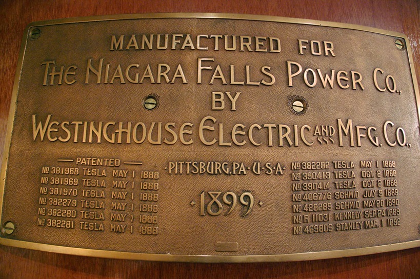
381968 - 381969 - 381970 - 382279 - 382280 - 382281 - 382282 - 390413 - 390414
Tesla's Laboratory Generator

Above: Tesla designed 2-phase motor/generator of the type used to power Tesla's Egg of Columbus in the New York laboratories. Tesla had exclusive access to a 500 h.p. two-phase generator circuit at the 1893 World's Fair. This type motor/generator served in New York in many roles in various sizes. They were used as iso/synchronous motors. This same type machine was also used in Colorado Springs, and the Wardenclyffe laboratories. Click image for more information.
Tesla requested, and obtained, Westinghouse company support in the manufacture of a powerful public demonstration model of the "Egg", which included a large two-phase generator power supply. The system was designed by Tesla, built to his specifications, and credit was given by Martin to "Mr. C. F. Scott, electrician of the Westinghouse Electric and Manufacturing Company" for the construction of the "Egg of Columbus" demonstrated at the World's Fair in 1893... But Remember, Tesla had been using his hand crafted Egg for at least 5 years prior as a research and development tool.
Why is this important?
This is important for several reasons. 1) Martin was prevented by Tesla from disclosing technology, means, or methods, that were not specifically patent protected, unless Tesla himself had decided to disclose proprietary research, which he sometimes did in public demonstrations, such as at the 1893 World's Fair, in lectures, and in articles published under his name. Tesla got to the point he could not patent everything, so he focused on key technology, and key geometry, and he often gave tidbits away in areas he had looked into, but was perhaps no longer actively researching. In other areas he gave away critical means and methods because he knew he was so far ahead that the technology he was demonstrating was critically incomplete. To get the cutting edge you had to visit the lab and get vibrated, and get illuminated.
The electromagnetic geometry disclosed by Tesla in the "Egg of Columbus" appears in Tesla's patent portfolio over, and over, and over again. It is patented as a motor field, - a generator field, - and a transformer
- And it is well documented in all of these applications in the Martin book.
Martin is very clear in his introduction that Tesla was not disclosing everything.
But 2) at the end of the book, in the section covering Tesla's exhibit at the World's Fair, Martin recounts his first hand witnessing of a public demonstration of Tesla's Egg of Columbus:
"The field produced was very powerful and exhibited striking effects, revolving copper balls and eggs and bodies of various shapes at considerable distances and great speeds."
Then there is this account, recorded in the Electrical Experimenter, March, 1919:
"But the demonstration which most imprest the audiences was the simultaneous operation of numerous balls, pivoted discs and other devices placed in all sorts of positions and at considerable distances from the rotating field. When the currents were turned on and the whole animated with motion, it presented an unforgettable spectacle. Mr. Tesla had many vacuum bulbs in which small, light metal discs were pivotally arranged on jewels and these would spin anywhere in the hall when the iron ring was energized."
So 3) Tesla's "Egg of Columbus", a motor demonstration device, was also the first transmitter geometry he (or anyone) used to produce a field which coupled to, and rotated, wireless motor armatures.
Once the World's Fair was over, the Egg of Columbus constructed by Mr. C.F. Scott apparently escaped the fire that consumed the S. Fifth Ave laboratory, or it was replaced with a nearly identical device because photographs clearly show an "Egg" of substantial construction, similar or identical to the one photographed at the World's Fair, in the Houston St. laboratory. See the pdf on "Tesla's Egg of Columbus", they are crediting Albert Schmid for the Egg in that photo. It is documented that the two-phase generator powering the Egg was operated by Tesla with up to 200 horsepower output for these demonstrations. I am confident that Tesla was using a powerful DC generator to excite the field windings of the 2-phase generator that was supplying the Egg: external excition up to 550 volts would really help a lot in getting 200 HP alternating current output.
It is recorded somewhere, and when I come across the reference I will note it in here, that Tesla was asked after the demonstration of the Egg at the World's Fair, why the Egg was not patented as a transmitter for wireless motors? Tesla replied that the coupling between the field generator or "transmitter", which is the ring of divided iron with four coils wound on it, and the receiving motor armature, is strictly inductive: it has no great range, and it could only be used to power small, local area networks, like the demonstration devices located on tables and shelves around the Houston Street laboratory. But Tesla stated that it provided a "starting point" for his research. And this is crucial to understanding Tesla's wireless.
So understanding and reproducing Tesla's wireless technology requires an understanding that he did not start his wireless research with resonating coils of copper wire, he started with a ring made of sub-divided iron, each piece of iron wire or ring of iron sheet in the core was electrically insulated from it's neighbor, typically shellac was used. The core was then clamped up into a form with a potting compound of some type, then tightly bound with cord to prevent internal vibration. Then it was wound with four heavy coils of #10, or heavier, enamel coated magnet wire... And that is where a proper investigation of Tesla's wireless technology begins.
By the time the Egg was demonstrated at the World's Fair, Tesla's work on induction motors was complete. He used every trick and technique in his motor patents to produce an Egg design and power supply that amazed witnesses. Tesla specified the Bessimer steel (really a high grade soft iron) and balanced the mass of copper and iron in layers, first a layer of heavy enamel magnet wire, then a layer of iron. There was a layer of cloth material soaked in shellac tightly binding each layer of iron and copper as the Egg was built up. Tesla surely used a large bank of capacitors, unseen in the photos and hidden from the witnesses, but patented specifically in 455,067 and 464,666 to cancel out all or most of the inductive reactive created by the massive windings. The iron winding surrounding the copper acts as a secondary, and care must be taken to ensure the rotating magnetic field does not result in a rotating current in the iron.
It can be boring, and tedious... Motors are not producing exciting plasma fireworks like Tesla's sparking coils... But Tesla's motor and generator development are key to understanding Tesla's thought processes, and the starting point for his wireless research. Tesla filed a complete patent on his wireless motor technology on May 20, 1889: included in the patent; a small to medium size commercial motor for powering a workshop or small vehicle say a golf cart; a desktop demonstration model, very inexpensive and simple to build; and an industrial motor, suitable for powering a bus, or a train: 424,036 - Electro-Magnetic Motor - May 20, 1889. The filing of the wireless motor patent occurred years before Tesla's wireless work is generally recognized as having begun, even today. People are under the impression that large resonating coils are the beginning of Tesla's wireless development, but a careful examination of the documentation clearly shows that understanding Tesla's process, understanding his development of wireless, starts right here, with understanding the basic physics of producing the rotating magnetic field in closed rings of insulated, sub-divided, iron.
Before we move on to Tesla's paper I want to add a couple more notes of interest. With a powerful two-phase generator at his disposal at the World's Fair, and afterwards at the Houston Street laboratory, Tesla poured on the steam. In order to obtain more output from the generator, the shaft speed, and therefore the line frequency, was increased. As the frequency increases the characteristics of the energy that is produced changes. Direct Current energy is not the same as alternating current energy, and low frequency alternating current has different properties than high-frequency currents. It is standard to use 400 Hz alternating current systems on aircraft instead of 60 cycle power systems because transformers require much less iron at 400 Hz. The circuits are physically smaller, and lighter, because things like the capacitor values required get smaller at higher frequencies. So for the most part, the technology presented and covered here is all designed to be constructed and operated in systems with frequencies well below 400 Hz, and we should all recognize this technology in our 60 cycle system, where heavy iron cores are an advantage, not a liability. The other thing to note are the diagrams: this paper was prepared in a hurry according to Martin, Tesla wrote it in pencil overnight. But many of the block prints are professional draft quality. This is because they were they prepared and used for the various patent applications covering this technology, and a professional draftsman did indeed create them.
You also may want to read the short introduction that Thomas Commerford Martin wrote for this paper in his book.
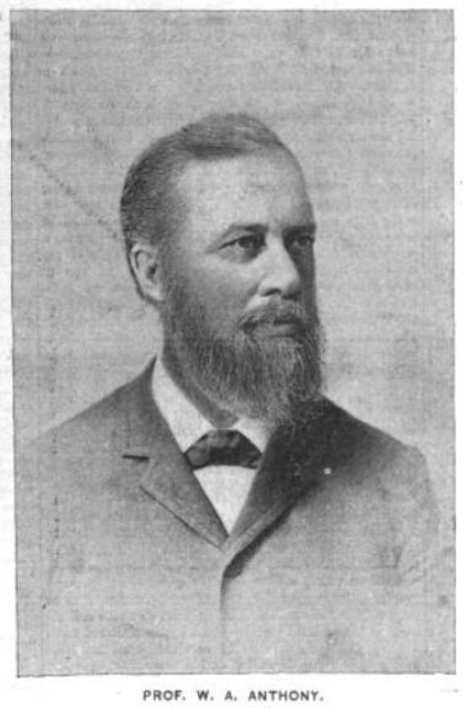
William Arnold Anthony
Professor of Physics, Chemistry, Mechanical, and Electrical Engineering, later president of the AIEE.
Quoting Nikola Tesla:
I desire to express my thanks to Professor Anthony for the help he has given me in this matter. I would also like to express my thanks to Mr. Pope and Mr. Martin for their aid. The notice was rather short, and I have not been able to treat the subject so extensively as I could have desired, my health not being in the best condition at present. I ask your kind indulgence, and I shall be very much gratified if the little I have done meets your approval.
In the presence of the existing diversity of opinion regarding the relative merits of the alternate and continuous current systems, great importance is attached to the question whether alternate currents can be successfully utilized in the operation of motors. The transformers, with their numerous advantages, have afforded us a relatively perfect system of distribution, and although, as in all branches of the art, many improvements are desirable, comparatively little remains to be done in this direction. The transmission of power, on the contrary, has been almost entirely confined to the use of continuous currents, and notwithstanding that many efforts have been made to utilize alternate currents for this purpose, they have, up to the present, at least as far as known, failed to give the result desired. Of the various motors adapted to be used on alternate current circuits the following have been mentioned: 1. A series motor with subdivided field. 2. An alternate current generator having its field excited by continuous currents. 3. Elihu Thomson's motor. 4. A combined alternate and continuous current motor. Two more motors of this kind have suggested themselves to me. 1. A motor with one of its circuits in series with a transformer and the other in the secondary of the transformer. 2. A motor having its armature circuit connected to the generator and the field coils closed upon themselves. These, however, I mention only incidentally.
The subject which I now have the pleasure of bringing to your notice is a novel system of electric distribution and transmission of power by means of alternate currents, affording peculiar advantages, particularly in the way of motors, which I am confident will at once establish the superior adaptability of these currents to the transmission of power and will show that many results heretofore unattainable can be reached by their use; results which are very much desired in the practical operation of such systems and which cannot be accomplished by means of continuous currents.
Before going into a detailed description of this system, I think it necessary to make a few remarks with reference to certain conditions existing in continuous current generators and motors, which, although generally known, are frequently disregarded. In our dynamo machines, it is well known, we generate alternate currents which we direct by means of a commutator, a complicated device and, it may be justly said, the source of most of the troubles experienced in the operation of the machines. Now, the currents so directed cannot be utilized in the motor, but they must -- again by means of a similar unreliable device -- be reconverted into their original state of alternate currents. The function of the commutator is entirely external, and in no way does it affect the internal working of the machines. In reality, therefore, all machines are alternate current machines, the currents appearing as continuous only in the external circuit during their transit from generator to motor. In view simply of this fact, alternate currents would commend themselves as a more direct application of electrical energy, and the employment of continuous currents would only be justified if we had dynamos which would primarily generate, and motors which would be directly actuated by such currents.

See: US Patent 381,968 - Figs. 1-8
But the operation of the commutator on a motor is twofold; firstly, it reverses the currents through the motor, and secondly, it effects, automatically, a progressive shifting of the poles of one of its magnetic constituents. Assuming, therefore, that both of the useless operations in the system, that is to say, the directing of the alternate currents on the generator and reversing the direct currents on the motor, be eliminated, it would still be necessary, in order to cause a rotation of the motor, to produce a progressive shifting of the poles of one of its elements, and the question presented itself, -- How to perform this operation by the direct action of alternate currents! I will now proceed to show how this result was accomplished.

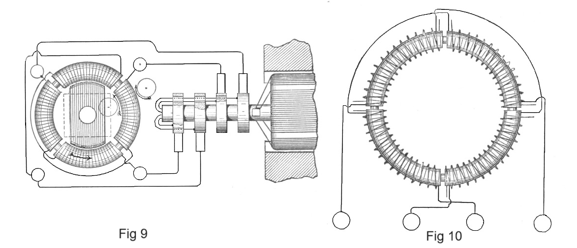
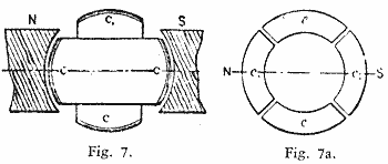
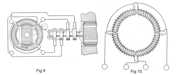
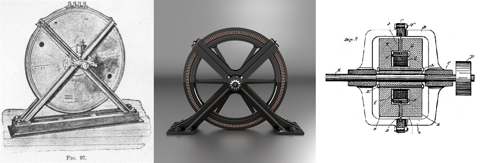
In the first experiment a drum-armature was provided with two coils at right angles to each other, and the ends of these coils were connected to two pairs of insulated contact-rings as usual. A ring was then made of thin insulated plates of sheet-iron and wound with four coils, each two opposite coils being connected together so as to produce free poles on diametrically opposite sides of the ring. The remaining free ends of the coils were then connected to the contact-rings of the generator armature so as to form two independent circuits, as indicated in figure 9. It may now be seen what results were secured in this combination, and with this view I would refer to the diagrams, figures 1 to 8a. The field of the generator being independently excited, the rotation of the armature sets up currents in the coils CC, varying in strength and direction in the well-known manner. In the position shown in figure 1 the current in coil C is nil while Coil C is traversed by its maximum current, and the connections my be such that the ring is magnetized by the coils c1 c1 as indicated by the letters N S in figure la, the magnetizing effect of the coils c c being nil, since these coils are included in the circuit of coil C.
In figure 2 the armature coils are shown in a more advanced position, one-eighth of one revolution being completed. Figure 2a illustrates the corresponding magnetic condition of the ring. At this moment the coil cl generates a current of the same direction as previously, but weaker, producing the poles nl sl upon the ring; the coil c also generates a current of the same direction, and the connections may be such that the coils c c produce the poles n s, as shown in figure 2a. The resulting polarity is indicated by the letters N S, and it will be observed that the poles of the ring have been shifted one-eighth of the periphery of the same.
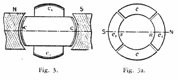
In figure 3 the armature has completed one-quarter of one revolution. In this phase the current in coil C is maximum, and of such direction as to produce the poles N S in
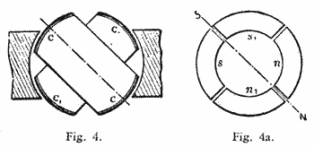
Figure 4 shows the coils C C in a still more advanced position, the armature having completed three-eighths of one revolution. At that moment the coil C still generates a current of the same direction as before, but of less strength, producing the comparatively weaker poles n s in figure 4a, The current in the coil C1 is of the same strength, but of opposite direction. Its effect is, therefore, to produce upon the ring the Poles n1 and sl as indicated, and a polarity, N S, results, the poles now being shifted three-eighths of the periphery of the ring.
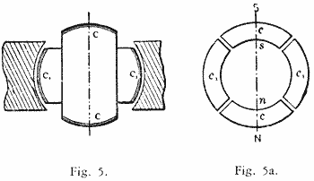
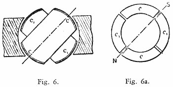
In figure 5 one-half of one revolution of the armature is completed, and the resulting magnetic condition of the ring is indicated in figure 5a. Now, the current in coil C is nil, while the coil C1 yields its maximum current, which is of the same direction aspreviously; the magnetizing effect is, therefore, due to the coils cl cl alone, and, referring to figure 5a, it will be observed that the poles N S are shifted one-half of the circumference of the ring. During the next half revolution the operations are repeated, as represented in the figures G to 8a.
A reference to the diagrams will make it clear that during one revolution of the armature the poles of the ring are shifted once around its periphery, and each revolution producing like effects, a rapid whirling of the poles in harmony with the rotation of the armature is the result. If the connections of either one of the circuits in the ring are reversed, the shifting of the poles is made to progress in the opposite direction, but the operation is identically the same. Instead of using four wires, with like result, three wires may be used, one forming a common return for both circuits. This rotation or whirling of the poles manifests itself in a series of curious phenomena. If a delicately pivoted disc of steel or other magnetic metal is approached to the ring it is set in rapid rotation, the direction of rotation varying with the position of the disc. For instance, noting the direction outside of the ring it will be found that inside the ring it turns in an opposite direction, while it is unaffected if placed in aposition symmetrical to the ring. This is easily explained. Each time that a pole approaches it induces an opposite pole in the nearest point on the disc, and an attraction is produced upon that point; owing to this, as the pole is shifted further away from the disc a tangential pull is exerted upon the same, and the action being constantly repeated, a more or less rapid rotation of the disc is the result. As the pull is exerted mainly upon that part which is nearest to the ring, the rotation outside and inside, or right and left, respectively, is in opposite directions, figure 9. When placed symmetrically to the ring, the pull on opposite sides of the disc being equal, no rotation results. The action is based on the magnetic inertia of the iron; for this reason a disc of hard steel is much more affected than a disc of soft iron, the latter being capable of very rapid variations of magnetism. Such a disc has proved to be a very useful instrument in all these investigations,
as it has enabled me to detect any irregularity in the action. A curious effect is also produced upon iron filings. By placing some upon a paper and holding them externally quite close to the ring they are set in a vibrating motion, remaining in the same place, although the paper may be moved back and forth; but in lifting the paper to a certain height which seems to be dependent on the intensity of the poles and thc speed of rotation, they are thrown away in a direction always opposite to the supposed movement of the poles. If a paper with filings is put flat upon the ring and the current turned on suddenly; the existence of a magnetic whirl may be easily observed.
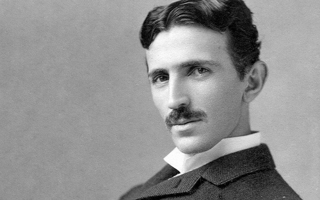
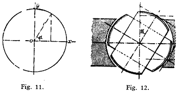
To demonstrate the complete analogy between the ring and a revolving magnet, a strongly energized electro-magnet was rotated by mechanical power, and phenomena identical in every particular to those mentioned above were observed. Obviously, the rotation of the poles produces corresponding inductive effects and may be utilized to generate currents in a closed conductor placed within the influence of the poles. For this purpose it is convenient to wind a ring with two sets of superimposed coils forming respectively the primary and secondary circuits, as shown in figure 10. In order to secure the most economical results the magnetic circuit should be completely closed, and with this object in view the construction may be modified at will.
The inductive effect exerted upon the secondary coils will be mainly due to the shifting or movement of the magnetic action; but there may also be currents set up in the circuits in consequence of the variations in the intensity of the poles. However, by properly designing the generator and determining the magnetizing effect of the primary coils the latter element may be made to disappear. The intensity of the poles being maintained constant, the action of the apparatus will be perfect, and the same result will bc secured as though the shifting were effected by means of a commutator with an infinite number of bars. In such case the theoretical relation between the energizing effect of each set of primary coils and their resultant magnetizing effect may be expressed by the equation of a circle having its center coinciding with that of an orthogonal system of axes, and in which the radius represents the resultant and the co-ordinates both of its components. These are then respectively the sine and cosine of the angle U between the radius and one of the axes (O X). Referring to figure 1 I, we have r2 = x2 + y2; where x = r cos a, and y = r sin a.
Assuming the magnetizing effect of each set of coils in the transformer to be proportional to the current -- which may be admitted for weak degrees of magnetization -- then x = Kc and y = Kcl, where K is a constant and c and cl the current in both sets of coils respectively. Supposing, further, the field of the generator to be uniform, we have for constant speed cl = K1 sin a and c = K1 sin (90o + a) = K1 cos a. where K1 is a constant. See figure 12.
Therefore, x = Kc = K K1 cos a;
y=Kcl=K K1 sin a, and
KK1 = r.
That is, for a uniform field the disposition of the two coils at right angles will secure the theoretical result, and the intensity of the shifting poles will be constant. But from r2 = x2 + y2 it follows that for y = O, r = x; it follows that the joint magnetizing effect of both sets of coils should be equal to the effect of one set when at its maximum action. In transformers and in a certain class of motors the fluctuation of the poles is not of great importance, but in another class of these motors it is desirable to obtain the theoretical result.
In applying this principle to the construction of motors, two typical forms of motor have been developed. First, a form having a comparatively small rotary effort at the start, but maintaining a perfectly uniform speed at all loads, which motor has been termed synchronous. Second, a form possessing a great rotary effort at the start, the speed being dependent on the load. These motors may be operated in three different ways: 1. By the alternate currents of the source only. 2. By a combined action of these and of induced currents. 3. By the joint action of alternate and continuous currents.
US Patent 382,280 - Fig 9 US Patent 381,970 - Fig 1
The simplest form of a synchronous motor is obtained by winding a laminated ring provided with pole projections with four coils, and connecting the same in the manner before indicated. An iron disc having a segment cut away on each side may be used as an armature. Such a motor is shown in figure 9. The disc being arranged to rotate freely within the ring in close proximity to the projections, it is evident that as the poles are shifted it will, owing to its tendency to place itself in such a position as to embrace the greatest number of the lines of force, closely follow the movement of the poles, and its motion will be synchronous with that of the armature of the generator; that is, in the peculiar disposition shown in figure 9, in which the armature produces by one revolution two current impulses in each of the circuits. It is evident that if, by one revolution of the armature, a greater number of impulses is produced, the speed of the motor will be correspondingly increased. Considering that the attraction exerted upon the disc is greatest when the same is in close proximity to the poles, it follows that such a motor will maintain exactly the same speed at all loads within the limits of its capacity.
To facilitate the starting, the disc may be provided with a coil closed upon itself. The advantage secured by such a coil is evident. On the start the currents set up in the coil strongly energize the disc and increase the attraction exerted upon the same by the ring, and currents being generated in the coil as long as the speed of the armature is inferior to that of the poles, considerable work may be performed by such a motor even if the speed be below normal. The intensity of the poles being constant, no currents will be generated in the coil when the motor is turning at its normal speed.
Instead of closing the coil upon itself, its ends may be connected to two insulated sliding rings, and a continuous current supplied to these from a suitable generator. The proper way to start such a motor is to close the coil upon itself until the normal speed is reached, or nearly so, and then turn on the continuous current. If the disc be very strongly energized by a continuous current the motor may not be able to start, but if it be weakly energized, or generally so that the magnetizing effect of the ring is preponderating it will start and reach the normal speed. Such a motor will maintain absolutely the same speed at all loads. It has also been found that if the motive power of the generator is not excessive, by checking the motor the speed of the generator is diminished in synchronism with that of the motor. It is characteristic of this form of motor that it cannot be reversed by reversing the continuous current through the coil.
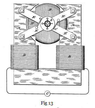
The synchronism of these motors may be demonstrated experimentally in a variety of ways. For this purpose it is best to employ a motor consisting of a stationary field magnet and an armature arranged to rotate within the same, as indicated in figure 13. In this case the shifting of the poles of the armature produces a rotation of the latter in the opposite direction. It results therefrom that when the normal speed is reached, the poles of the armature assume fixed positions relatively to the field magnet and the same is magnetized by induction, exhibiting a distinct pole on each of the pole-pieces. If a piece of soft iron is approached to the field magnet it will at the start be attracted with a rapid vibrating motion produced by the reversals of polarity of the magnet, but as the speed of the armature increases; the vibrations become less and less frequent and finally entirely cease. Then the iron is weakly but permanently attracted, showing that the synchronism is reached and the field magnet energized by induction.
The disc may also be used for the experiment. If held quite close to the armature it will turn as long as the speed of rotation of the poles exceeds that of the armature; but when the normal speed is reached, or very nearly so; it ceases to rotate and is permanently attracted.
A crude but illustrative experiment is made with an incandescent lamp. Placing the lamp in circuit with the continuous current generator, and in series with the magnet coil, rapid fluctuations are observed in the light in consequence of the induced current set up in the coil at the start; the speed increasing, the fluctuations occur at longer intervals, until they entirely disappear, showing that the motor has attained its normal speed.
A telephone receiver affords a most sensitive instrument; when connected to any circuit in the motor the synchronism may be easily detected on the disappearance of the induced currents.
In motors of the synchronous type it is desirable to maintain the quantity of the shifting magnetism constant, especially if the magnets are not properly subdivided.
To obtain a rotary effort in these motors was the subject of long thought. In order to secure this result it was necessary to make such a disposition that while the poles of one element of the motor are shifted by the alternate currents of the source, the poles produced upon the other element should always be maintained in the proper relation to the former, irrespective of the speed of the motor. Such a condition exists in a continuous current motor; but in a synchronous motor, such as described, this condition is fulfilled only when the speed is normal.
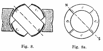
See: US Patent 381,969 - Fig 1
The object has been attained by placing within the ring a properly subdivided cylindrical iron core wound with several independent coils closed upon themselves. Two coils at right angles as in figure 14, are sufficient, but greater number may he advantageously employed. It results from this disposition that when the poles of the ring are shifted, currents are generated in the closed armature coils. These currents are the most intense at or near the points of the greatest density of the lines of force, and their effect is to produce poles upon the armature at right angles to those of the ring, at least theoretically so; and since action is entirely independent of the speed -- that is, as far as the location of the poles is concerned -- a continuous pull is exerted upon the periphery of the armature. In many respects these motors are similar to the continuous current motors. If load is put on, the speed, and also the resistance of the motor, is diminished and more current is made to pass through the energizing coils, thus increasing the effort. Upon the load being taken off, the counter-electromotive force increases and less current passes through the primary or energizing coils. Without any load the speed is very nearly equal to that of the shifting poles of the field magnet.
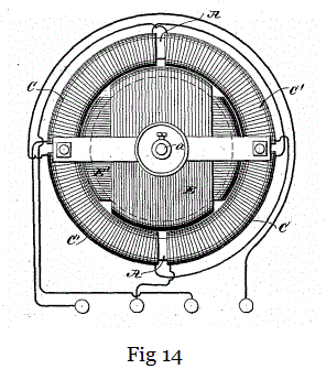
See: US Patent 382,279 - Fig 1
It will be found that the rotary effort in these motors fully equals that of the continuous current motors. The effort seems to be greatest when both armature and field magnet are without ally projections; but as in such dispositions the field cannot be very concentrated, probably the best results will be obtained by leaving pole projections on one of the elements only. Generally, it may be stated that the projections diminish the torque and produce a tendency to synchronism.
A characteristic feature of motors of this kind is their capacity of being very rapidly reversed. This follows from the peculiar action of the motor. Suppose the armature to be rotating and the direction of rotation of the poles to be reversed. The apparatus then represents a dynamo machine, the power to drive this machine being the momentum stored up in the armature and its speed being the sum of the speeds of the armature and the poles. If we now consider that the power to drive such a dynamo would be very nearly proportional to the third power of the speed, for this reason alone the armature should be quickly reversed. But simultaneously with the reversal another element is brought into action, namely, as the movement of the poles with respect to the armature is reversed, the motor acts like a transformer in which the resistance of the secondary circuit would be abnormally diminished by producing in this circuit an additional electromotive force. Owing to these causes the reversal is instantaneous. If it is desirable to secure a constant speed, and at the same time a certain effort at the start, this result may be easily attained in a variety of ways. For instance, two armatures, one for torque and the other for synchronism, may be fastened on the same shaft, and any desired preponderance may be given to either one, or an armature may be wound for rotary effort, but a more or less pronounced tendency to synchronism may be given to it by properly constructing the iron core; and in many other ways.
As a means of obtaining the required phase of the currents in both the circuits, the disposition of the two coils at right angles is the simplest, securing the most uniform action; but the phase may be obtained in many other ways, varying with the machine employed. Any of the dynamos at present in use may be easily adapted for this purpose by making connections to proper points of the generating coils. In closed circuit armatures, such as used in the continuous current systems, it is best to make four derivations from equi-distant points or bars of the commutator, and to connect the same to four insulated sliding rings on thc shaft. In this case each of the motor circuits is connected to two diametrically opposite bars of the commutator. In such a disposition the motor may also be operated at half the potential and on the three-wire plan, by connecting the motor circuits in the proper order to three of the contact rings.
In multipolar dynamo machines, such as used in the converter systems, the phase is conveniently obtained by winding upon the armature two series of coils in such a manner that while the coils of one set or series are at their maximum production of current, the coils of the other will be at their neutral position, or nearly so, whereby both sets of coils may be subjected simultaneously or successively to the inducing action of thc field magnets.
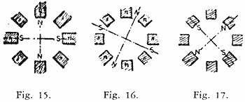
Generally the circuits in the motor will be similarly disposed, and various arrangements may be made to fulfill the requirements; but the simplest and most practicable is to arrange primary circuits on stationary parts of the motor, thereby obviating, at least in certain forms, the employment of sliding contacts. In such a case thc magnet coils are connected alternately in both the circuits; that is 1, 3, 5....... in one, and 2, 4, 6...... in the other, and the coils of each set of series may be connected all in the same manner, or alternately in opposition; in the latter case a motor with half the number of poles will result, and its action will be correspondingly modified. The figures 15, 16 and 17, show three different phases, the magnet coils in each circuit being connected alternately in opposition. In this case there will be always four poles, as in figures 15 and 17, four pole projections will be neutral, and in figure 16 two adjacent pole projections will have the same polarity. If the coils are connected in the same manner there will be eight alternating poles, as indicated by the letters n' s' in fig.15.
The employment of multipolar motors secures in this system an advantage much desired and unattainable in the continuous current system, and that is, that a motor may be made to run exactly at a predetermined speed irrespective of imperfections in construction, of the load, and, within certain limits, of electromotive force and current strength.
In a general distribution system of this kind the following plan should be adopted. At the central station of supply a generator should be provided having a considerable number of poles. The motors operated from this generator should be of the synchronous type, but possessing sufficient rotary effort to insure their starting. With the observance of proper rules of construction it may be admitted that the speed of each motor will be in some inverse proportion to its size, and the number of poles should be chosen accordingly. Still exceptional demands may modify this rule. In view of this, it will be advantageous to provide each motor with a greater number of pole projections or coils, the number being preferably a multiple of two and three. By this means, by simply changing the connections of the coils, the motor may be adapted to any probable demands. If the number of the poles in the motor is even, the action will he harmonious and the proper result will be obtained; if this is not the case the best plan to be followed is to make a motor with a double number of poles and connect the same in the manner before indicated, so that half the number of poles result. Suppose, for instance, that the generator has twelve poles, and it would be desired to obtain a speed equal to 12/7 of the speed of the generator. This would require a motor with seven pole projections or magnets, and such a motor could not be properly connected in the circuits unless fourteen armature coils would be provided, which would necessitate the employment of sliding contacts. To avoid this the motor should be provided with fourteen magnets and seven connected in each circuit, the magnets in each circuit alternating among themselves. The armature should have fourteen closed coils. The action of the motor will not be quite as perfect as in the case of an even number of poles, but the drawback will not be of a serious nature.
However, the disadvantages resulting from this unsymmetrical form will be reduced in the same proportion as the number of the poles is augmented.
If the generator has, say, n, and the motor n1 poles, the speed of the motor will be equal to that of the generator multiplied by n/n1.
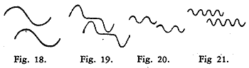
The speed of the motor will generally be dependent on the number of the poles, but there may be exceptions to this rule. The speed may be modified by the phase of the currents in the circuits or by the character of the current impulses or by intervals between each or between groups of impulses. Some of the possible cases are indicated in the diagrams, figures l8, l9, 20 and 2l, which are self-explanatory. Figure 18 represents the condition generally existing, and which secures the best result. In such a case, if the typical form of motor illustrated in figure 9 is employed, one complete wave in each circuit will produce one revolution of the motor. In figure 19 the same result will he effected by one wave in each circuit, the impulses being successive; in figure 20 by four, and in figure 21 by eight waves.
By such means any desired speed may be attained; that is, at least within the limits of practical demands. This system possesses this advantage besides others, resulting from simplicity. At full loads the motors show efficiency fully equal to that of the continuous current motors. The transformers present an additional advantage in their capability of operating motors. They are capable of similar modifications in construction, and will facilitate the introduction of motors and their adaptation to practical demands. Their efficiency should be higher than that of the present transformers, and I base my assertion on the following:
In a transformer as constructed at present we produce the currents in the secondary circuit by varying the strength of the primary or exciting currents. If we admit proportionality with respect to the iron core the inductive effect exerted upon the secondary coil will be proportional to the numerical sum of the variations in the strength of the exciting current per unit of time; whence it follows that for a given variation any prolongation of the primary current will result in a proportional loss. In order to obtain rapid variations in the strength of the current, essential to efficient induction, a great number of undulations are employed. From this practice various disadvantages result. These are, increased cost and diminished efficiency of the generator, more waste of energy in heating the cores, and also diminished output of the transformer, since the core is not properly utilized, the reversals being too rapid. The inductive effect is also very small in certain phases, as will be apparent from a graphic representation, and there may be periods of inaction, if there are intervals between the succeeding current impulses or waves. In producing a shifting of the poles in the transformer, and thereby inducing currents, the induction is of the ideal character, being always maintained at its maximum action. It is also reasonable to assume that by a shifting of the poles less energy will be wasted than by reversals.
Previous Chapter --- Contents --- Next Chapter
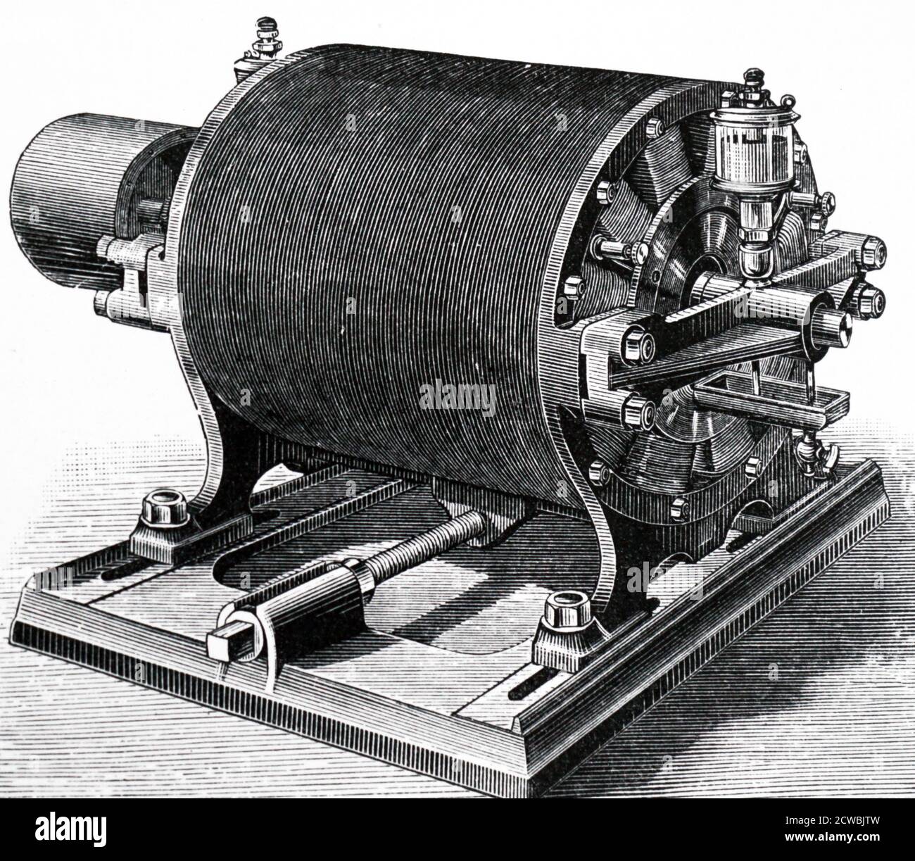
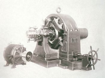
Early Tesla 2-phase motor constructed in Tesla's laboratory. This design was developed from the prototype motor shown in Fig 299 in the Martin Book. This engraving was made from a photograph taken in early 1888.
Click for a higher resolution image.
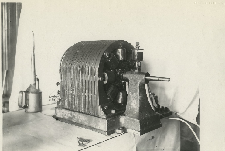
Prototype production line Tesla 2-phase motor photographed at the Westinghouse Electric and Manufacturing Company Pittsburgh facility in 1888. This general construction plan, with manufacturing and efficiency improvements, was scaled up to 500 hp production line motors by 1891 and were exhibited at the 1893 World's Fair.
Image courtesy of https://historicpittsburgh.org/collection/westinghouse-electric-corporation-photographs
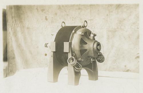
Early Westinghouse production line Tesla 2-phase motor constructed and photographed in Pittsburgh. This motor is based on the perfected prototype motor "N" that was photographed in Tesla's laboratory in early 1888, and was displayed at the 1893 World's Fair. Larger clones of the motor "N", with a heavier duty bearing support as shown above, were used to power rotational equipment in the Electricity Building exhibits.
Detre Library & Archives, Heinz History Center. Hosted by: University of Pittsburgh Library System
To the Archive Page Discussion on Tesla's Wireless
Lab-Tesla disclosures on the technology just presented
NEXT Tesla Lecture
EXPERIMENTS WITH ALTERNATE CURRENTS OF VERY HIGH FREQUENCY AND THEIR APPLICATION TO METHODS OF ARTIFICIAL ILLUMINATION