Nikola Tesla's Laboratory Power
Boiler, Steam Engine, Line-Shaft, Belts & Pulleys
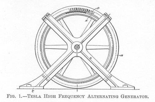
These are modern museum photos, the video demonstrates this technology. Click on the diagram above for the Wiki page.
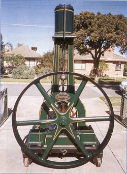
~10 horsepower, brewery type engine - typically ground grain and pumped liquids. - 1877
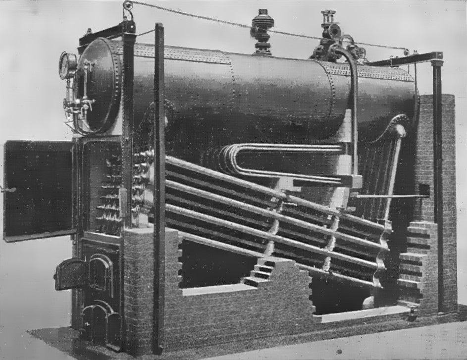
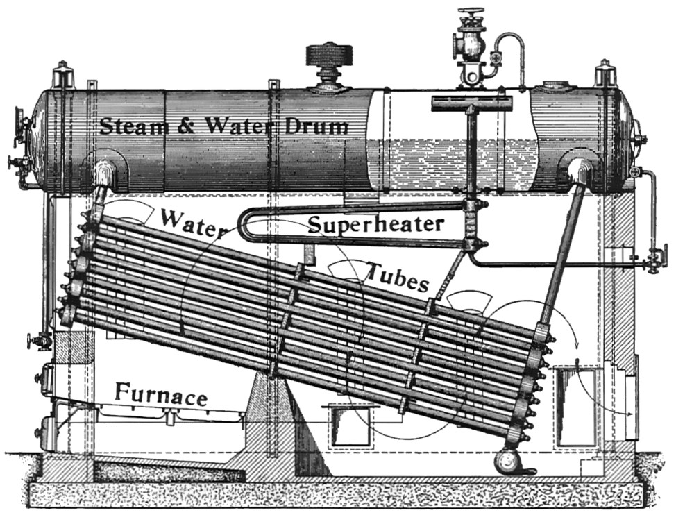
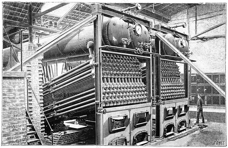
The above image is a Babcock and Wilcox water-tube boiler of the exact type Tesla used in New York. It is shown labeled, below. Tesla contacted the firm's headquarters and requested a high-pressure design: the steam was superheated to a much higher degree than normal, and the construction was accordingly more robust. This same type boiler, fired with oil, was demonstrated at the 1893 World's Fair.
45 horsepower, 33.1 kiloWatt, double-action, 2-cylinder marine engine built prior to 1880. Engines like this were available used mid-decade.
From the 1870's on, steam engines were advancing by leaps and bounds. Horsepower-to-weight ratios for both engines and boilers improved dramatically. The US Patent Office saw new engines, and improvements, every day. Engines were available for practically every application: pumps and conveyors of all kinds, machine shops, wood working shops, mills; and in New York at the time, both new, and used, marine engines were available. The technology was advancing so quickly that perfectly servicable machines only a few years old were considered obsolete and were frequently sold second hand very reasonably to someone who could move the heavy equipment. Tesla was in a position to purchase broken or damaged machinery and then effect the repairs himself.
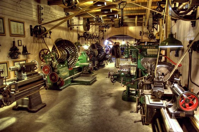
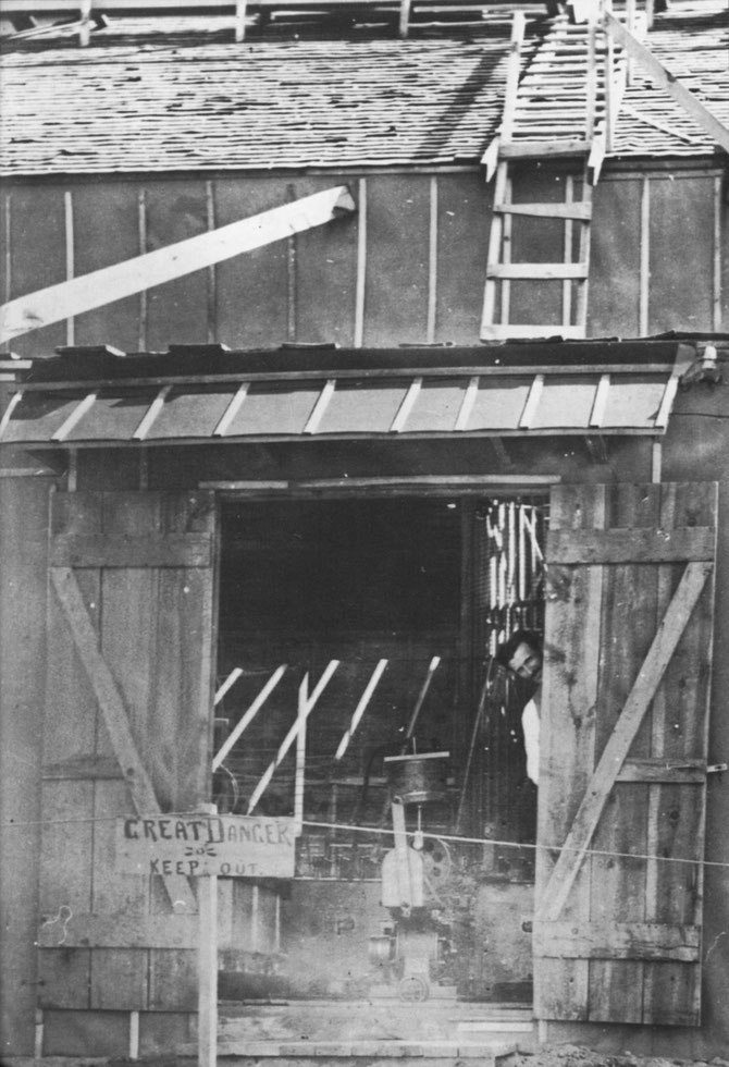
Tesla leased space in commerical buildings with flooring that could withstand the weight of heavy equipment, and structurally strong enough to install overhead line-shafts. In the basement there was a boiler(s), burning coal, like everyone else in New York at the time, with a stack venting outside. Steam from the boiler was plumbed to an engine with a flywheel. Belted to the flywheel was the line-shaft. The line-shaft ran through the shop and experiment area. Belts were dropped down to power things like generators and dynamos; to produce electrical power, run experiments, and perform demonstrations; but line-shaft power was also used to run lathes, drill press, mill, and other shop tools required to construct prototype machines and laboratory equipment. Tesla contracted out to a foundry for the castings he needed, but most of the machining work was done in the laboratory shop area. Steam was also a laboratory utility used in the manufacture of condensers, coils, and other devices, in addition to driving all of the isochronous oscillators and generators, which were based on Tesla patented reciprocating steam engines.
Steam driven line shaft power was also used for pumps to produce compressed air, and liquified air.
From the mid 1880's, all the way until Wardenclyffe, Tesla's laboratory fully qualified as a heavy commercial or light-industrial concern. There are strong indications that Tesla's Rahway, New Jersey facility ran 20+/7: In the morning, steam engine power was primarily used to run belt driven shop equipment; in the afternoon and evening the "Dynamo-Electric Machine" was clutched in and alternating current was taken off the slip rings for laboratory research and development in accordance with US Patent 390,414. Overnight; a fireman was employed to maintain steam and monitor the boiler, engine, and generator while DC power was taken off the commutator to provide for street lighting [See: arc-lights]. The fireman would leave at dawn, the fire would die down for a few hours. When the morning shift of clerks and machinists showed up, a new fireman would dump the ashes from the night before and restoke the firebox, quickly having steam up to run belt driven shop tools. Tesla would have a fireman maintain steam from dawn to nightfall whenever possible so he could have the entire output for experimental use. Tesla arranged his work hours around the available power: it would be difficult to share a line shaft with a machine shop while engaged in R&D, because loads are frequently clutched in and out, and the resulting dragging and over-speeds make measurements impossible; and trying to work around a heavy load like an arc-lamp system can result in both electrical and mechanical failures. So the loads were divided into time slots: the machinists came in early, Tesla came in late. He checked on the morning's work progess, took care of the day's paperwork, and sometimes took a nap and went out for a meal while the machinists were putting loads on the line-shaft power supply. In the early afternoon shop workers were given instructions for the next days work and went home. Tesla kept a fireman, an assistant, and frequently a clerk would still be in the office. After the move to New York from Rahway, New Jersey, Tesla no longer provided overnight power for street lighting, and he had exclusive night use of the boilers and engines for research, development, and demonstrations for lab visitors.
Above: First Westinghouse commercial/industrial polyphase Tesla generator, photographed in the power shack of the Ames hydroelectric plant outside Telluride, Colorado. This generator is wired for single-phase power transmission: Armature geometry by Schmid-Tesla. If you look closely on the left side of the image, you can see the substantial drum belt pulley, and the drive belt. This Tesla generator was driven by the water turbine invented by Lester Allan Pelton in the 1870's.
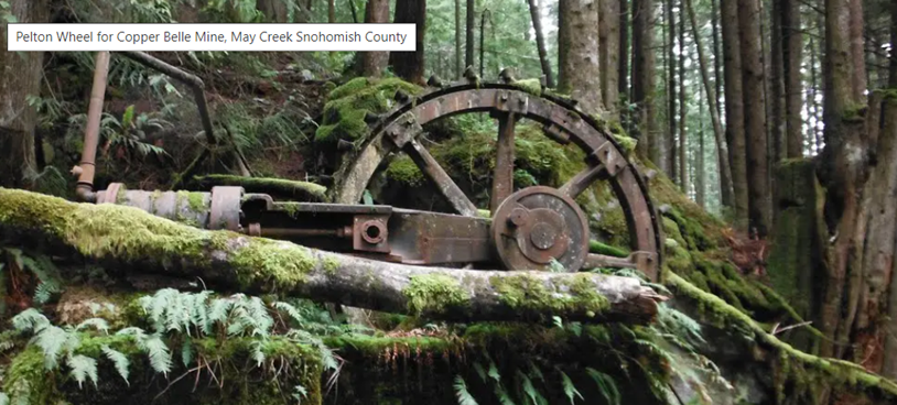
Above: This is a very late 1800's or very early 1900's Pelton wheel installation for a Washington state copper mine. Fragments at this site show a previous wheel, much older than the wheel photographed, that shattered: so this is a later installation on the original foundation and penstock run. This installation used a high pressure penstock pipe made of wooden staves bound with threaded iron rings and nuts. It's long gone. Only the hand dug trough and rusted 30 inch (at the top) down to 12 inch (at the bottom) iron rings with frozen nuts remain of the high pressure penstock pipe at this site. The primary job of this wheel was running direct drive Ingersoll air compressors (one seen in photo, there is another compressor cylinder on the opposite side) for operating mine drills. This installation also included a small (30 h.p.) Westinghouse generator.
By the 1880's the Pelton Wheel was powering a number of large mills in America, and some were powering DC generators for local lighting, and applications like electric street cars. So the industrial water turbines (both Pelton and Francis turbines) and line-shaft technology to convert water elevation drop into industrial rotational force, was well developed in America before Tesla came on the scene. Hydraulic mining had developed reservoirs, flumes, and pressurized plumbing (penstock) systems, some of which still operates today over 150 years after hydraulic mining was outlawed, that were converted/adapted to Pelton wheel applications.
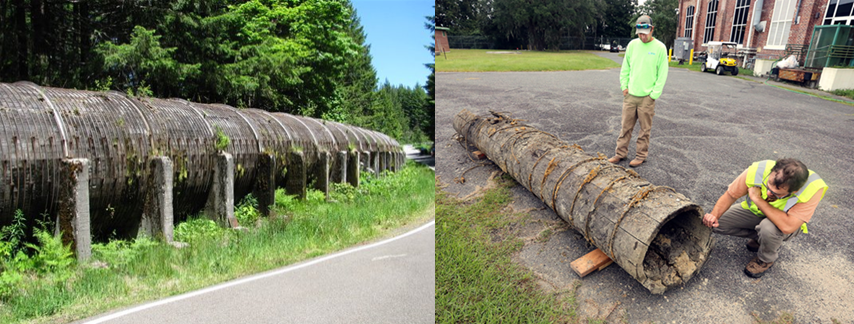
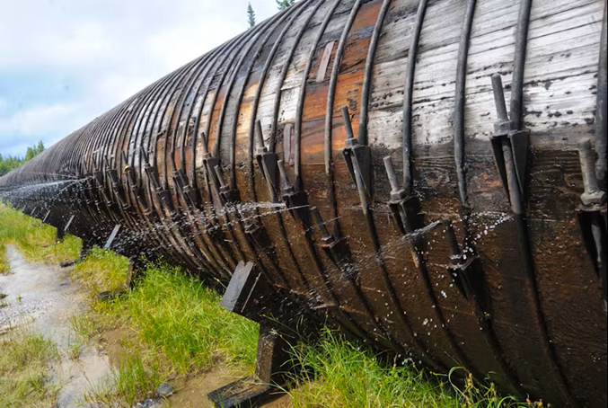
"Corner Brook Pulp and Paper" maintains wooden penstock pipes for hydroelectric generation to this very day I believe. They replaced some old wooden penstocks with fiberglass prior to 2018, but they still had wooden stave penstock pipe under pressure in 2020. I include these photos specifically because this is the exact technology that powered Tesla's Colorado Springs Oscillator for the infamous spark photos.
Mining was one of the first applications for smaller wheels: they ran compressors to operate drills and ventilate mines. Water was dammed upstream and then diverted to the wheel through wooden and iron penstock plumbing. High water pressure was developed as the penstock pipe ran down hill. As the pipe descended, it was narrowed, developing additional hydraulic pressure. The water pressure that was produced at the bottom of the penstock was directed through an iron nozzle, called "The Monitor" in hydraulic mining, into the cups mounted on the bottom of the Pelton wheel, turning the wheel and running the air compressor. Small generators were later sometimes included to provide electrical lighting for the mines.
The critical problem at this point in the historcal record was the transmission of energy (industrial rotational force) over any significant distance. Not all mines had water with an elevation drop within a mile or two of the shaft entrance. Those mines without water power turned their wheels with steam. Pelton and Francis turbines were off the shelf, and regularly applied whenever they could be used. Tesla solved the long distance transmission problem.
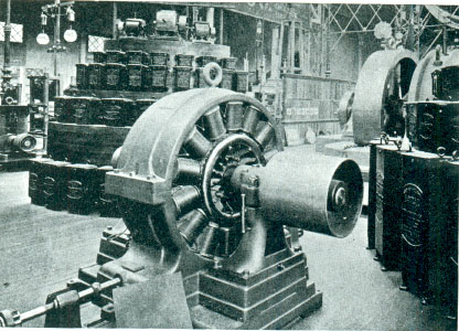
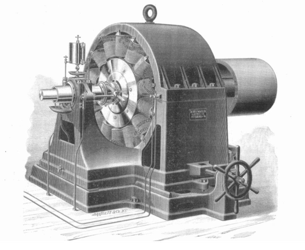
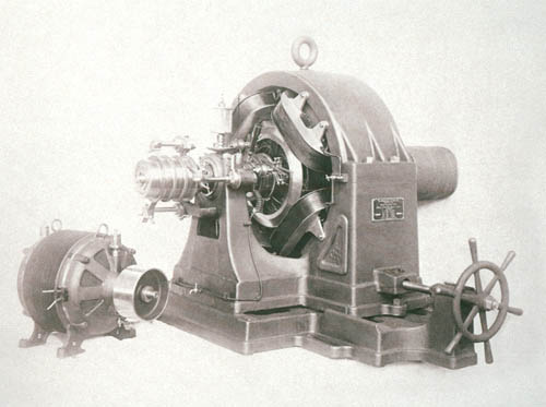
Production line 100 hp Westinghouse synchronous polyphase Motor/Generator on the exhibit floor at the Chicago World's Fair, Columbian Exposition, 1893
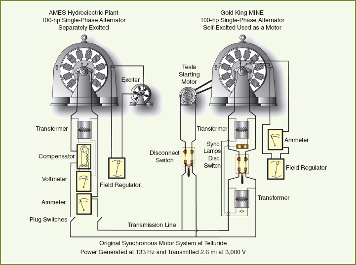
The problem at the Gold King Mine (GKM) was they needed industrial power at the mine entrance, and there was no way to run a 100 horsepower line-shaft from the turbine to the mine. They had packed a steam engine and wheel up the mountain in parts, and then assembled it on site where they needed the power, but they were running out of timber that could be cut and economically hauled to supply the boiler. They had already tried a DC system, but the losses and voltage drop over the 3 mile (4.83 km) run to the mine meant the DC motor would not pull a load, and the cables overheated. The energy was needed to drive a rock crusher (stamp mill) to process ore.
Tesla systems share properties with linked particles.
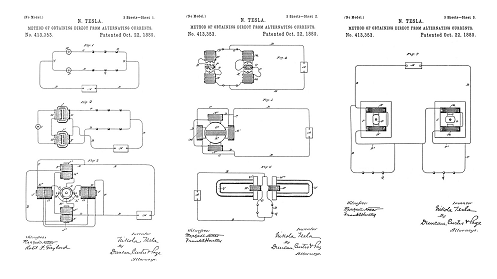
The schematic for the generator, transformer, transmission line, and large synchronous motor. See US Patent 401,520 and 405,859. This system also requires regulators to control the field electromagnets. The schematic is not clear, but it is likely that Tesla employed a moderately sized synchronous motor as the compensator for this system. This system, as shown in diagram, was demonstrated with two-phases, four wires, using 500 h.p. motor/generators at the Tesla/Westinghouse exhibit at the 1893 World's Fair.
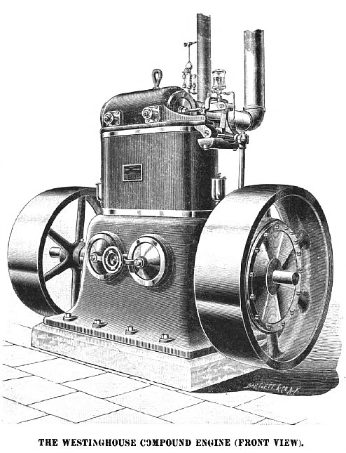
By 1888 Westinghouse had developed compound steam engines which were then matched to Tesla's 2-phase alternators. Click images for more information/higher resolution.
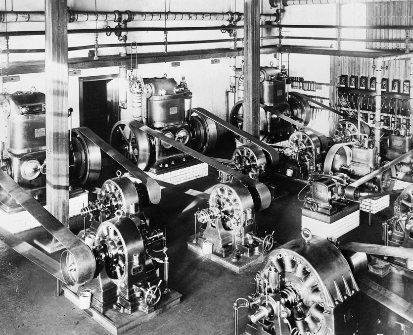
Westinghouse equipment in a power plant.
The above photo was taken in the powerhouse of the Allegheny Light Company. These were first generation production line Tesla/Westinghouse generators driven with Westinghouse compound steam engines, the photo is dated circa 1888. As the demand for power grew, they simply added in more boilers, engines, and generators to meet the increasing demand. The boilers were hand-fed coal fired. The generators were also very high-maintanence, they had a flow through lubrication system for the main bearings, and you can see the catch buckets used to collect the drip oil. A generator technician would have to fill the drip cups to feed the bearings, then collect the oil from the drip buckets, strain it, and refill the drip cups. The belts had to be adjusted frequently, using the spike wheel cranks on the equipment base. Getting caught in a belt could easily tear a limb off.
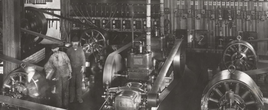
Image courtesy of: Historic Pittsburgh Org
A good powerhouse engineer with a crew of technicians can keep a setup like this running and stay ahead of big maintanence problems, but you have to be sharp. You have to monitor each drip bucket for oil color: metal flake from the bearings produces silvery colored oil and is a warning sign. Same with metal fragments picked up when straining the drip buckets. You have to keep a very close eye on the equipment and you have to be extremely careful not to get caught in it. The pickup rings on the generator shafts are all live, 133 Hz.
The above image shows one of Nikola Tesla's work areas at the Westinghouse Electric and Manufacturing Co. facilities in Pittsburgh, PA.. This photo was taken early in 1889 during the period of time when Tesla was employed daily as a consultant to Westinghouse and his staff. During this period Tesla worked closely with Albert Schmid and Charles F. Scott on the design and construction of industrial machines based on the patents Westinghouse had purchased from Tesla, and others. Prototype production motors are on the table, oil drip cups installed, these are clones of the 2-phase motor "N" that Tesla exhibited at the 1893 World's Fair.. You can see the knife switches are wired and open for each motor, so test runs were taking place. Tesla's 2-phase motors operated better at a lower frequency than the 133 Hz lighting frequencies that had been standardized in Westinghouse power plants at this time. The industrial scaling of the Tesla polyphase system was set for 60 cycle operation during this period to accommodate the motors. Before Tesla's consulting term was over, Westinghouse hired Benjamin G. Lamme to work with Charles Scott for the continuing polyphase development program in house. Upon leaving Pittsburgh later that year, Tesla immediately went into higher frequency research in New York.
At this point in time, Tesla's laboratory in New York was equipped with a coal fired standard pressure boiler of high capacity. A Westinghouse compound engine supplied power for the line-shaft that ran through the laboratory upstairs. Tesla had the high pressure boiler added about this time. The money from the sale of his patents to Westinghouse, and income from his consulting job in Pittsburgh, were already being invested in upgraded research facilties in NY. When Tesla left Pittsburgh after one year, he went to work in NY again in completely upgraded facilities. There were two boilers, two engines, multiple generators.
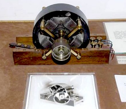
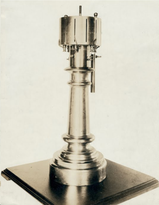
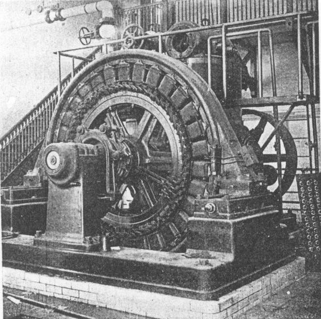
Figure 298a - Early Tesla 2-phase, alternating current, motor/generator.
Above right: Tesla designed, Westinghouse manufactured, 2-phase motor/generator of the type used to power Tesla's Egg of Columbus in the New York laboratories. This type generator head was also used as an iso/synchronous motor in New York. These machines were photographed in service at Colorado Springs, and in the Wardenclyffe laboratories (photos below). They were used as generators and motors, including frequency locked motors, in various sizes, power levels, and speeds. The smaller 2-phase motor on the lower left is a Westinghouse Electric and Manufacturing Co. clone of the 2-phase motor "N" that Tesla displayed at the 1893 World's Fair.
While the equipment and schematic above document a single-phase 100 horsepower Tesla motor/generator system of the type Tesla used (sans motor) to produce the famous spark photos taken in the Colorado Springs laboratory: Tesla's first dedicated alternating current motor/generators were much smaller 2-phase machines shown in Fig 298a above. Much of this early equipment was detailed by Martin is his section on Tesla's exhibit at the World's Fair, but the setups Tesla used in his own lab applied all of the wiring and circuit components documented in the photos and schematic diagrams above, only there were 2-phases instead of one.
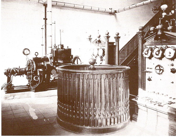
Tesla maintained 2-phase commercial generators that were constructed by Westinghouse. These generators were belted off of the steam driven line-shaft and this provided alternating current to demonstrate Tesla's Egg of Columbus. These generators also produced the power to drive the iron-core high-voltage transformers used to charge capacitors in his electrical oscillator that supplied the high-frequency laboratory lighting. Tesla used the lighting patent he had developed for his own laboratory and shop lighting. The oscillator also required circulating oil, and the oil pump was driven by a Tesla patented induction motor, powered from the same patented 2-phase generator. These generators are shown in photo, and in patent, with belt drives, unless they are directly shaft coupled to rotational power supplies.

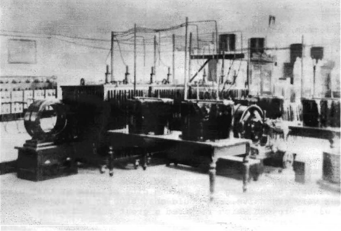
In this photo above, taken in the NY laboratory, a slightly modified 2-phase generator is shown belted and running in the lower right. The power take off slip-rings are out of view behind a square plate, this plate may have held terminals on the opposite side for a shaft-driven synchronous rotary gap. In the photo above you can see cables, probably carrying 110 volt DC, used to power the generator field electromagnets. This generator was rarely operated in self-excited mode, because too much line-shaft power is lost to producing the generator magnetic field when the generator is self-excited, and the power output is reduced. In the left rear of the above image you can see the tank with two terminals, well insulated, coming from the lid. This is U.S. Patent 514,168 which was used for the laboratory lighting ballast transformer. There is another partial view of this machine photographed at Tesla's Exhibit at the World's Fair and was included in the Martin Book as Fig 311.
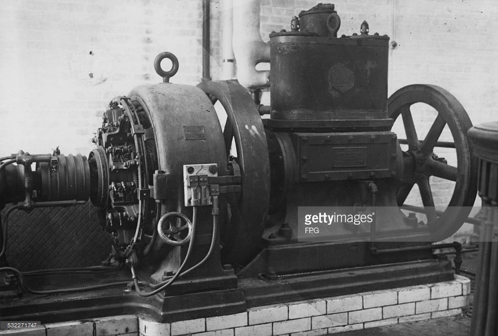
If you look at the above photo closely, on the floor you can see the same type 2-phase generator. The slip-ring mechanisms are hidden with a protective cover, on the left side of the generator shaft. The right side of the generator has the belt pulley removed and it is directly shaft-coupled to a skid mounted engine of some type, likely a prairie tractor engine, out of view. This was surely a section of reinforced flooring, and this equipment was used for low-power testing and set up of the large oscillator. It is reported that Tesla obtained up to 200 horsepower from this particular generator when operated on the New York laboratory boiler and engine. 550 volts DC was available in the Colorado Springs laboratory building here, and could have been used for excitation current, but Tesla patented proprietary technology for self-excitation and that could also be employed. The power levels here were at first limited by the horsepower of the engine, but the Westinghouse generator at the Colorado Springs Power Company produced the full plate rated 100 hp output.
In Colorado Springs, Tesla used the generator head above for low power testing and set up. The Colorado Springs Electric Co. was owned by a friend of Tesla's by the name of Stanley Curtis. The power company had 3 generators at the time Tesla was in Colorado: there were two of the Westinghouse 100 h.p. generators, identical to the unit photographed in the Ames power shack, and a 550 volt DC generator for a trolley line in Colorado Springs. After 10 pm, the trolley did not run, and at night the city of Colorado Springs only used a fraction of the output from one of the two 100 h.p. Westinghouse generators. After 10 pm, Tesla had the entire output of one of the two 100 h.p. generators at his disposal, and a 550 volt DC line. In order to produce a pure harmonic series, including sine wave outputs, from the extra-coil at Colorado Springs, Tesla used the 550 volt DC line to charge capacitors, and switched the oscillator with a liquid mercury switch. This test model would produce the same functions electrically as the Wardenclyffe transmitter. The spark photos of the Colorado Springs oscillator were produced using the 100 h.p. Westinghouse generator as the power supply and the output was a complex harmonic transform: A pulse wave linked together with a continous harmonic series, but because of the alternating current power supply and the lack of an isochronous generator to lock in the fundamental frequency meant the output was only suitable for testing and model development purposes. The photos were taken to demonstate power processing efficiencies and peak power levels obtained in the oscillator. In a functional transmitter all of the high voltage output from the oscillator, visually seen in the spark photos, would be trapped on a large open ended capacitor, and upon reversal of the oscillator polarity the energy is forced into the ground.
Belts were still used at Wardenclyffe, they had to have a line-shaft to demonstrate and operate Tesla's patented dynamos and alternators; the line-shaft powered the belt driven shop equipment that was moved to Wardenclyffe from the New York lab; but photos and documentation show the main engines, generators, and line-shaft at Wardenclyffe were all direct drive, gear driven, rather than belted off of a common line-shaft that itself is belted off a steam-driven flywheel. Direct drive with grouted equipment greatly improves the signal quality, reliability, power delivery, and reduces maintainence.
Above: Front center is Tesla's wireless remote control torpedo boat: US Patent 613,809 -- On the far left, against the wall, is a brass stand/water filled radiator; mounted on top of the decorative water filled radiator base is a Tesla reciprocating steam engine driving clockwork: US Patent 514,169; this was used to power things like Tesla's rotational receivers, it was also used to rotate coherers at a constant speed. It turned stroboscopes, it was used to drive small alternating current generators to produce a pure sine wave output that was frequency locked. -- On the floor next to the steam oscillator is a cabinet sitting by itself with a liquid mercury rotary switch on top. -- Against the wall, on top of cabinets to the right of the steam oscillator, with horn-like stand off insulators, are a line of patented electrical isochronous oscillators. -- To the right of the electrical oscillators is a short drum coil form, supported with internal cross braces. This was a receiver test coil used in experiments and demonstrations of conjoint action.
In the end, the entire laboratory was intended to be a demonstration section inside the commerically operating Wardenclyffe plant. The dream was never realized in full; but at one point in time for a few years, Wardenclyffe had steam power, generators, transformers, and circuit controllers on site, all in operational condition. But the expense of maintaining the plant without a commerical income was more than Tesla could bear.
Lower center in the image above is a receiver table with a coil wound on the drum. The top cover could be removed and inside were capacitors and taps taken from the winding. The capacitance and inductance could be tuned to match the frequency of the transmitter circuit with a primary loop of cable that went around the laboratory ceiling molding. When the transmitter was energized the receiving table could light bulbs, produce sparks and corona, operate small motors etc.. All wirelessly.
The receiving table was inductive only, it would not work as a stand-alone device very far from the transmitter. But with a different transmitter geometry, and a grounded receiver, this technology represented an end user appliance for Tesla's wireless system. The grounded receiver appliance would pick up enough energy from the transmitter, conductively, to light reading lamps, and operate equipment like tikker tape receiving devices and Tesla's patented rotational receivers, and turning, as well as triggering, coherers. Tesla was talking about a system that could be developed to send facsimile, voice, and text to individual subscribers.
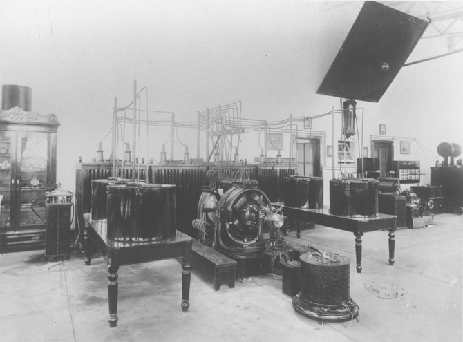
On the lower right in the image above is a cabinet with more electrical oscillators, some of these were set up and operated as desktop models of the large Wardenclyffe transmitter. Above and to the left a little, on metal wheels, is a matched pair of variable transformers for 2-phase work. Next, standing by itself near to the door is another steam powered isochronous mechanical oscillator. The 8 foot diameter spiral coil is suspended.
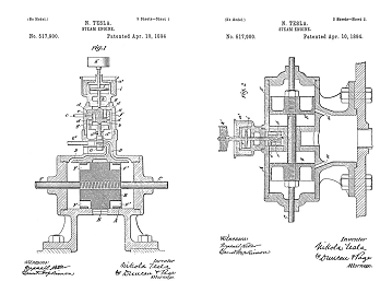
514,169 - Reciprocating Engine
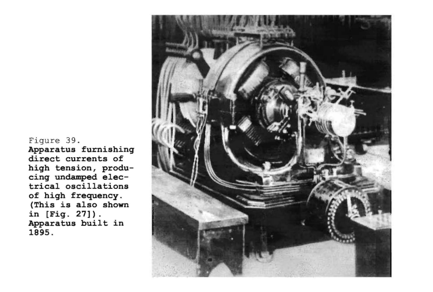
Tesla has the same type 2-phase motor/generator being powered in this application as a motor. This 2-phase motor is driving a high-voltage DC generator, just visible on the mount behind. The high-voltage DC is used to charge the main transmitter capacitors. In order for the transmitter to produce an accurate harmonic sine wave output from the discharge of high-voltage capacitors, the capacitors must be charged to the exact same voltage each and every time they are cycled. This pretty much rules out using alternating current as the main transmitter power supply. Direct current charging combined with precision switching of the capacitors is required to deliver a string of perfectly timed pulses, each pulse having exactly the same amplitude and duration. This is an on-site prototyping circuit used to energize the Wardenclyffe tower coils during low-power testing and development, but many of the components here were designed for full power operation.
Wardenclyffe had industrial, grouted, frequency stable, polyphase generators (shown above and below).
Above and below - Standard Westinghouse Lighting Plant with Tesla patented generator. The building lighting came from this generator, you can see a switch board in the upper image. Tesla had all of the electrical conduits designed into the building floor plans, the same way cabling is run in modern data centers. The main transmitter power and utilities equipment are shown running in an image further down the page.
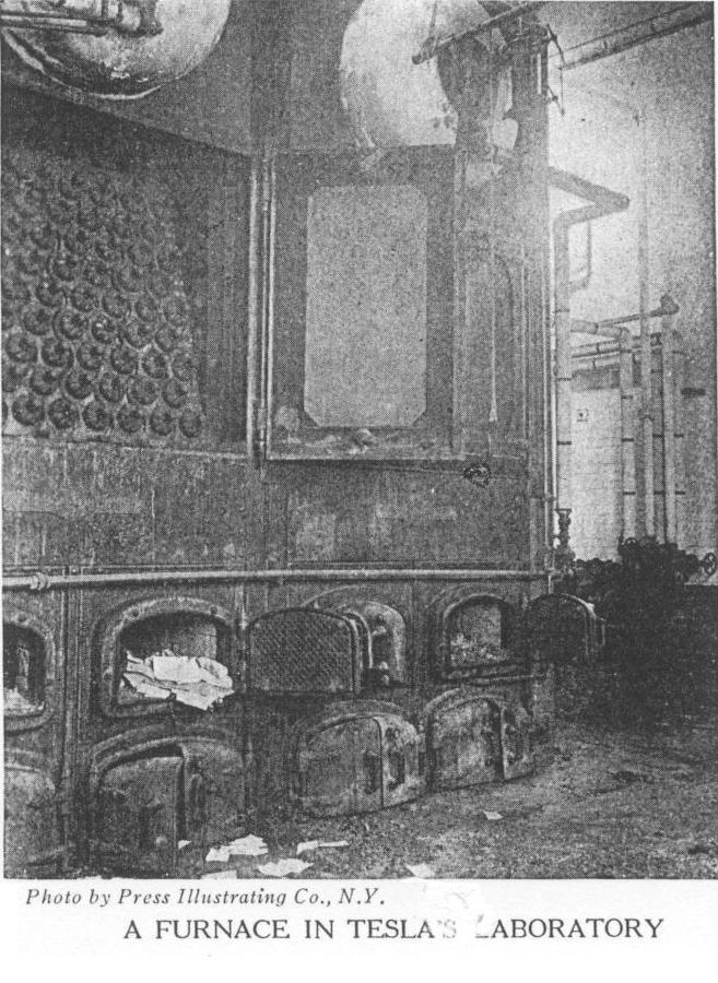
Babcock and Wilcox water-tube boilers in the Wardenclyffe plant, post 1902, above. Below is an illustration depicting the construction of the same type boiler - 1897. These boilers had been demonstrated, fired with oil, at the 1893 World's Fair, but hand shoveled coal was employed at Tesla's Wardenclyffe project.

All of the basic power technology here was developed and standardized by Westinghouse after the 1893 World's Fair. These exact type systems were well documented by multiple periodicals and books years before Tesla developed the Wardenclyffe property. See: The Electrical Engineer, April 26, 1893.
Even after he lost control of the property, and was no longer able to maintain laboratory space, he worked towards the future. He developed Fluid Dynamics technology, patented a high-energy internal combustion Turbine to replace steam piston power in his laboratory and next generation technology.
There is no such thing as "free energy"... Tesla burned coal to generate steam to drive a piston, and then a turbine. They harnessed the "free energy" of Niagara Falls, but it cost millions of dollars in 1890's money to construct the required infrastructure. Tesla's "free energy" motors are someone's fantasy: Tesla did patent wirelessly powered motors, but the transmitting power supplies include a generator. And generators require energy. Tesla wrote that in the future, humans would be able to harness the wheel-work of nature to turn our machines... But there is no secret industrial power source here. Self-excited alternators are not free energy devices, you still have to have some means to turn the armature: gasoline or other engine. Even if you were able to think up a way to directly tap energy off the earth's rotating magnetic field, it would still require the expense of equipment and very likely an exciting power supply...It costs money. About the only true "free energy" is drying your laundry in the sun and wind, as long as you have something, a line, to hang them on.
To the Archive Page Discussion on Tesla's Technology
The Story of Tesla's Work
Tesla's Cymatic Research
Steam Powered Isochronous Acoustic Oscillators & Generators
The Inventions, Researches, and Writings of
Nikola Tesla
Thomas Commerford Martin
Self-Exciting Dynamos and Alternators
Rectification, Energy Conversion
The Lectures of Dr. Nikola Tesla
All lectures are formatted with legible images of the original wood cut block prints
Tesla's Complete Patents
There are 111 unique Tesla Patents
Articles by Tesla