396,121
THERMO-MAGNETIC MOTOR - March 30, 1886
UNITED STATES PATENT OFFICE
NIKOLA TESLA, OF SMILJAN, LIKA, AUSTRIA-HUNGARY.
Nikola Tesla Patent 396,121 THERMO-MAGNETIC MOTOR
SPECIFICATION forming part of Letters Patent No. 396,121, dated January 15, 1889
Application filed March 30, 1886. Serial No. 197,115. (No model.)
To all whom it may concern:
Be it known that I, NIKOLA TESLA, of Smiljan, Lika, border country of Austria-Hungary, have invented an Improvement in Thermo-Magnetic Motors, of which the following is a specification.
It is well known that heat applied to a magnetized body will lessen the magnetism, and if the temperature is raised sufficiently the magnetism will be neutralized or destroyed.
In my present invention I obtain mechanical power by a reciprocating action resulting from the joint operations of heat, magnetism, and a spring or weight or other force—that is to say, I subject a body magnetized by induction or otherwise to the action of heat until the magnetism is sufficiently neutralized to allow a weight or spring to give motion to the body and lessen the action of the heat, so that the magnetism may be sufficiently restored to move the body in the opposite direction, and again subject the same to the demagnetizing of the heat.
In carrying out my invention I am able to make use of either an electro-magnet or a permanent magnet, and I preferably direct the heat against a body that is magnetized by induction, rather than directly against a permanent magnet, thereby avoiding the loss of magnetism that might result in the permanent magnet by the action of heat. I also provide for lessening the volume of the heat or for intercepting the same during that portion of the reciprocation in which the cooling action takes place.
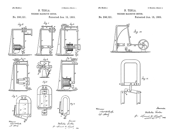
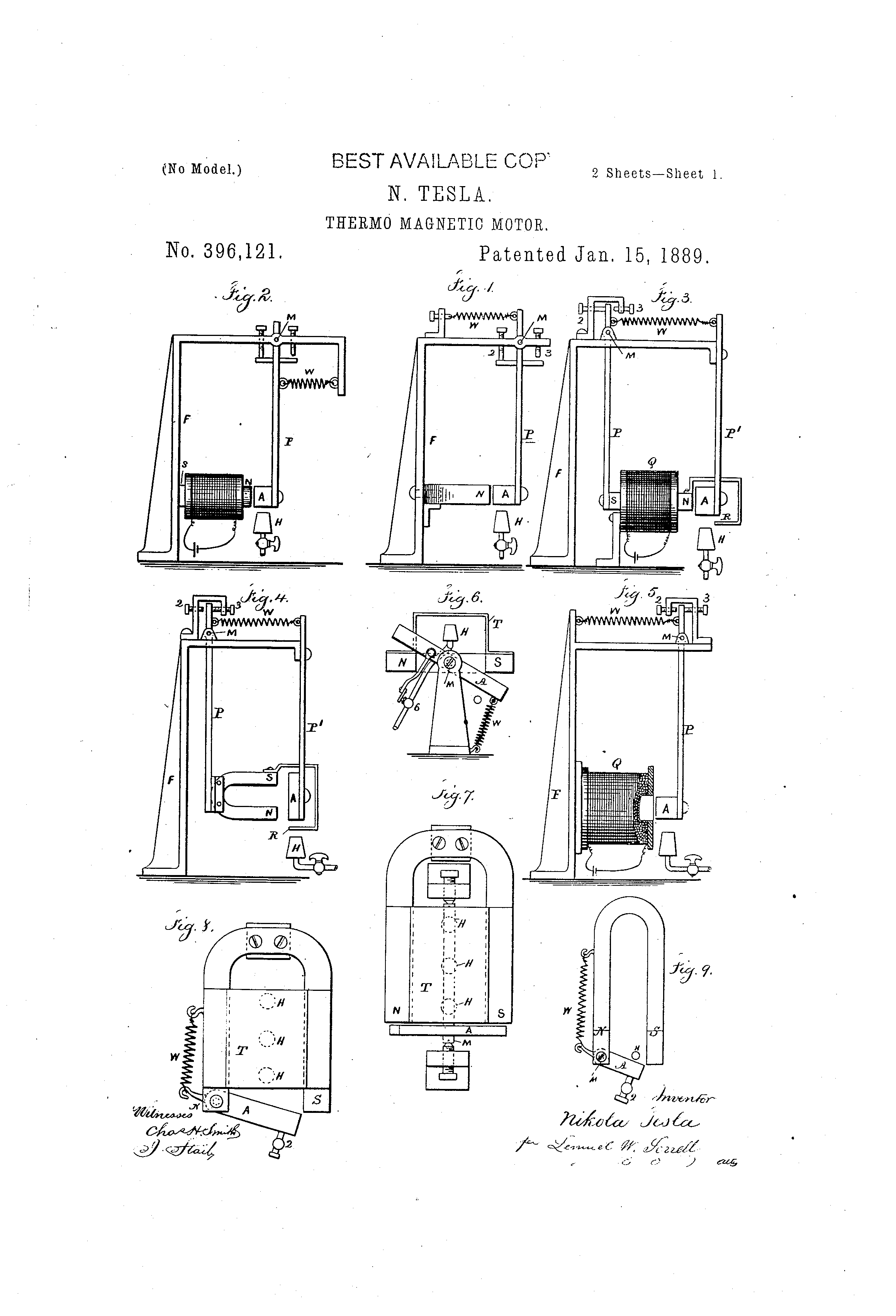
In the drawings I have represented by diagrams some of the numerous arrangements that may be made use of in carrying out my invention. In all of these figures the magnet-poles are marked N S, the armature A, the Bunsen burner or other source of heat H, the axis of motion M, and the spring or the equivalent thereof—namely, a weight—is marked W.
In Figure 1 the permanent magnet N is connected with a frame, F, supporting the axis M, from which the arm P hangs, and at the lower end of which the armature A is supported. The stops 2 and 3 limit the extent of motion, and the spring W tends to draw the armature A away from the magnet N. It is now to be understood that the magnetism of N is sufficient to overcome the spring W and draw the armature A toward the magnet N. The heat acting upon the armature A neutralizes its induced magnetism sufficiently for the spring W to draw the armature A away from the magnet N and also from the heat at H. The armature now cools and the attraction of the magnet N overcomes the spring W and draws the armature A back again above the burner H, so that the same is again heated and the operations are repeated. The reciprocating movements thus obtained are employed as a source of mechanical power in any desired manner. Usually a connecting-rod to a crank upon a fly-wheel shaft will be made use of, as indicated in Fig. 10; but I do not limit myself in this respect.
Fig. 2 represents the same parts as before described; but an electro-magnet is illustrated in place of a permanent magnet. The operations, however, are the same.
In Fig. 3 I have shown the same parts as in Figs. 1 and 2, only they are differently arranged. The armature A, instead of swinging, is stationary and held by an arm, P', and the core N S of the electro-magnet is made to swing within the helix Q, the said core being suspended by the arm P from the pivot M. A shield, R, is connected with the magnet-core and swings therewith, so that after the heat has demagnetized the armature A to such an extent that the spring W draws the core N S away from the armature A the shield R comes between the flame H and armature A, thereby intercepting the action of the heat and allowing the armature to cool, so that the magnetism, again preponderating, causes the movement of the core N S toward the armature A and the removal of the shield R from above the flame, so that the heat again acts to lessen or neutralize the magnetism. A rotary or other movement may be obtained from this reciprocation.
Fig. 4 corresponds in every respect with Fig. 3, except that a permanent horseshoe-magnet, N S, is represented as taking the place of the electro-magnet in said Fig. 3.
In Fig. 5 I have shown a helix, Q, with an armature adapted to swing toward or from the helix. In this case there may be a soft-iron core in the helix, or the armature may assume the form of a solenoid-core, there being no permanent core within the helix.
Fig. 6 is an end view, and Fig. 7 a plan view, illustrating my improvement as applied to a swinging armature, A, and a stationary permanent magnet, N S. In this instance I apply the heat to an auxiliary armature or keeper, T, which is adjacent to and preferably in direct contact with the magnet. This armature T, in the form of a plate of sheet-iron, extends across from one pole to the other and is of sufficient section to practically form a keeper for the magnet, so that when this armature T is cool nearly all the lines of force pass over the same and very little free magnetism is exhibited. Then the armature A, which swings freely on the pivots M in front of the poles N S, is very little attracted and the spring s pulls the same away from the poles into the position indicated in the drawings. The heat is directed upon the iron plate T at some distance from the magnet, so as to allow the magnet to be kept comparatively cool. This heat is applied beneath the plate by means of the burners H, and there is a connection from the armature A or its pivot to the gas-cock 6 or other device for regulating the heat. The heat acting upon the middle portion of the plate T, the magnetic conductivity of the heated portion is diminished or destroyed, and a great number of the lines of force are deflected over the armature A, which is now powerfully attracted and drawn into line, or nearly so, with the poles N S. In so doing the cock 6 is nearly closed and the plate T cools, the lines of force are again deflected over the same, the attraction exerted upon the armature A is diminished, and the spring W pulls the same away from the magnet into the position shown by full lines, and the operations are repeated. The arrangement shown in Fig. 6 has the advantages that the magnet and armature are kept cool and the strength of the permanent magnet is better preserved, as the magnetic circuit is constantly closed.
In the plan view, Fig. 8, I have shown a permanent magnet and keeper-plate, T, similar to those in Figs. 6 and 7, with the burners H for the gas beneath the same; but the armature is pivoted at one end to one pole of the magnet and the other end swings toward and from the other pole of the magnet. The spring W acts against a lever-arm that projects from the armature, and the supply of heat has to be partly cut off by a connection to the swinging armature, so as to lessen the heat acting upon the keeper-plate when the armature A has been attracted.
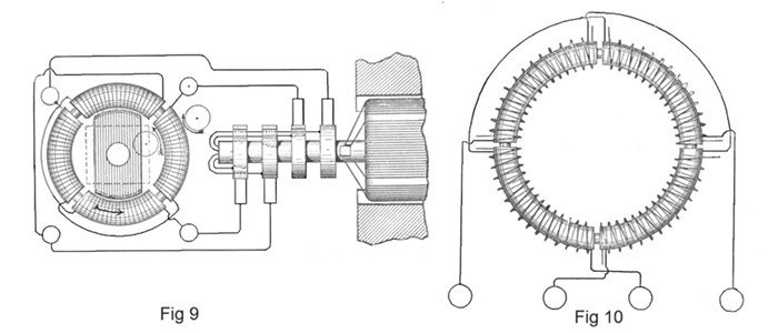
Fig. 9 is similar to Fig. 8, except that the keeper T is not made use of and the armature itself swings into and out of the range of the intense action of the heat from the burner H.
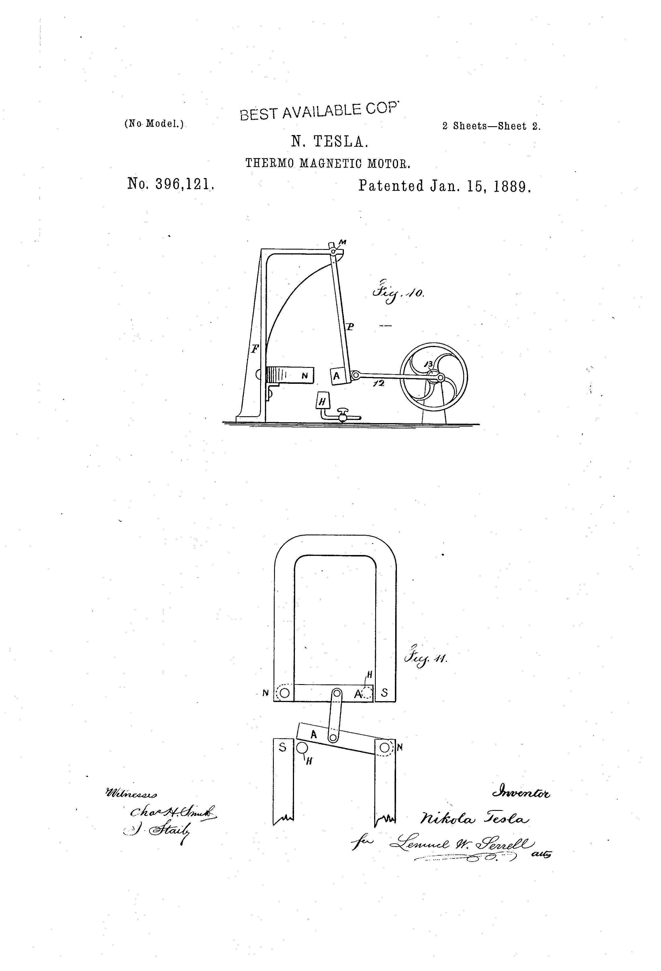
Fig. 10 is a diagram similar to Fig. 1, except that in place of using a spring and stops the armature is shown as connected by a link, 12, to the crank 13 of a fly-wheel, so that the fly-wheel will be revolved as rapidly as the armature can be heated and cooled to the necessary extent. A spring may be used in addition, as in Fig. 1.
In Fig. 11 the two armatures A A are connected by a link, so that one will be heating while the other is cooling, and the attraction exerted to move the cooled armature is availed of to draw away the heated armature instead of using a spring.
I have shown in the drawings several ways of carrying out my invention; but said invention is not limited by any particular form, arrangement, or construction of devices.
I claim as my invention—
1. The combination, with a swinging body under the influence of magnetism, of a burner or other source of heat acting to vary the magnetism, and a spring or other power to move the swinging body in the opposite direction to the action of the magnetism, substantially as set forth.
2. The combination, with two or more armatures connected to each other, of magnets to influence such armatures, and burners or other sources of heat to vary the magnetic action and cause the armatures to move, substantially as set forth.
Signed by me this 29th day of March, 1886.
NIKOLA TESLA
Click images for higher-resolution
Source File: US Patent 396,121 - pdf
Chapter XXXVI - The Martin Book
Thermo-Magnetic Motors and Pyro-Magnetic Generators
Thomas Commerford Martin
No electrical inventor of the present day dealing with the problems of light and power considers that he has done himself or his opportunities justice until he has attacked the subject of thermo-magnetism. As far back as the beginning of the seventeenth century it was shown by Dr. William Gilbert, the father of modern electricity, that a loadstone or iron bar when heated to redness loses its magnetism; and since that time the influence of heat on the magnetic metals has been investigated frequently, though not with any material or practical result.
For a man of Mr. Tesla's inventive ability, the problems in this field have naturally had no small fascination, and though he has but glanced at them, it is to be hoped he may find time to pursue the study deeper and further. For such as he, the investigation must undoubtedly bear fruit. Meanwhile he has worked out one or two operative devices worthy of note. He obtains mechanical power by a reciprocating action resulting from the joint operations of heat, magnetism, and a spring or weight or other force—that is to say he subjects a body magnetized by induction or otherwise to the action of heat until the magnetism is sufficiently neutralized to allow a weight or spring to give motion to the body and lessen the action of the heat, so that the magnetism may be sufficiently restored to move the body in the opposite direction, and again subject the same to the demagnetizing power of the heat.
Use is made of either an electro-magnet or a permanent magnet, and the heat is directed against a body that is magnetized by induction, rather than directly against a permanent magnet, thereby avoiding the loss of magnetism that might result in the permanent magnet by the action of heat. Mr. Tesla also provides for lessening the volume of the heat or for intercepting the same during that portion of the reciprocation in which the cooling action takes place.
In the diagrams are shown some of the numerous arrangements that may be made use of in carrying out this idea. In all of these figures the magnet-poles are marked N S, the armature A, the Bunsen burner or other source of heat H, the axis of motion M, and the spring or the equivalent thereof—namely, a weight—is marked W.
In Fig. 231 the permanent magnet N is connected with a frame, F, supporting the axis M, from which the arm P hangs, and at the lower end of which the armature A is supported. The stops 2 and 3 limit the extent of motion, and the spring W tends to draw the armature A away from the magnet N. It will now be understood that the magnetism of N is sufficient to overcome the spring W and draw the armature A toward the magnet N. The heat acting upon the armature A neutralizes its induced magnetism sufficiently for the spring W to draw the armature A away from the magnet N and also from the heat at H. The armature now cools, and the attraction of the magnet N overcomes the spring W and draws the armature A back again above the burner H, so that the same is again heated and the operations are repeated. The reciprocating movements thus obtained are employed as a source of mechanical power in any desired manner. Usually a connecting-rod to a crank upon a fly-wheel shaft would be made use of, as indicated in Fig. 240.
Fig. 232 represents the same parts as before described; but an electro-magnet is illustrated in place of a permanent magnet. The operations, however, are the same.
In Fig. 233 are shown the same parts as in Figs. 231 and 232, but they are differently arranged. The armature A, instead of swinging, is stationary and held by arm P', and the core N S of the electro-magnet is made to swing within the helix Q, the core being suspended by the arm P from the pivot M. A shield, R, is connected with the magnet-core and swings with it, so that after the heat has demagnetized the armature A to such an extent that the spring W draws the core N S away from the armature A, the shield R comes between the flame H and armature A, thereby intercepting the action of the heat and allowing the armature to cool, so that the magnetism, again preponderating, causes the movement of the core N S toward the armature A and the removal of the shield R from above the flame, so that the heat again acts to lessen or neutralize the magnetism. A rotary or other movement may be obtained from this reciprocation.
Fig. 234 corresponds in every respect with Fig. 233, except that a permanent horseshoe-magnet, N S is represented as taking the place of the electro-magnet in Fig. 233.
In Fig. 235 is shown a helix, Q, with an armature adapted to swing toward or from the helix. In this case there may be a soft-iron core in the helix, or the armature may assume the form of a solenoid core, there being no permanent core within the helix.
Fig. 236 is an end view, and Fig. 237 a plan view, illustrating the method as applied to a swinging armature, A, and a stationary permanent magnet, N S. In this instance Mr. Tesla applies the heat to an auxiliary armature or keeper, T, which is adjacent to and preferably in direct contact with the magnet. This armature T, in the form of a plate of sheet-iron, extends across from one pole to the other and is of sufficient section to practically form a keeper for the magnet, so that when the armature T is cool nearly all the lines of force pass over the same and very little free magnetism is exhibited. Then the armature A, which swings freely on the pivots M in front of the poles N S, is very little attracted and the spring W pulls the same way from the poles into the position indicated in the diagram. The heat is directed upon the iron plate T at some distance from the magnet, so as to allow the magnet to keep comparatively cool. This heat is applied beneath the plate by means of the burners H, and there is a connection from the armature A or its pivot to the gas-cock 6, or other device for regulating the heat. The heat acting upon the middle portion of the plate T, the magnetic conductivity of the heated portion is diminished or destroyed, and a great number of the lines of force are deflected over the armature A, which is now powerfully attracted and drawn into line, or nearly so, with the poles N S. In so doing the cock 6 is nearly closed and the plate T cools, the lines of force are again deflected over the same, the attraction exerted upon the armature A is diminished, and the spring W pulls the same away from the magnet into the position shown by full lines, and the operations are repeated. The arrangement shown in Fig. 236 has the advantages that the magnet and armature are kept cool and the strength of the permanent magnet is better preserved, as the magnetic circuit is constantly closed.
In the plan view, Fig. 238, is shown a permanent magnet and keeper plate, T, similar to those in Figs. 236 and 237, with the burners H for the gas beneath the same; but the armature is pivoted at one end to one pole of the magnet and the other end swings toward and from the other pole of the magnet. The spring W acts against a lever arm that projects from the armature, and the supply of heat has to be partly cut off by a connection to the swinging armature, so as to lessen the heat acting upon the keeper plate when the armature A has been attracted.
Fig. 239 is similar to Fig. 238, except that the keeper T is not made use of and the armature itself swings into and out of the range of the intense action of the heat from the burner H. Fig. 240 is a diagram similar to Fig. 231, except that in place of using a spring and stops, the armature is shown as connected by a link, to the crank of a fly-wheel, so that the fly-wheel will be revolved as rapidly as the armature can be heated and cooled to the necessary extent. A spring may be used in addition, as in Fig. 231. In Fig. 241 the armatures A A are connected by a link, so that one will be heating while the other is cooling, and the attraction exerted to move the cooled armature is availed of to draw away the heated armature instead of using a spring.
It will, of course, be inferred from the nature of these devices that the vibration obtained in this manner is very slow owing to the inability of the iron to follow rapid changes in temperature. In an interview with Mr. Tesla on this subject, the compiler learned of an experiment which will interest students. A simple horseshoe magnet is taken and a piece of sheet iron bent in the form of an L is brought in contact with one of the poles and placed in such a position that it is kept in the attraction of the opposite pole delicately suspended. A spirit lamp is placed under the sheet iron piece and when the iron is heated to a certain temperature it is easily set in vibration oscillating as rapidly as 400 to 500 times a minute. The experiment is very easily performed and is interesting principally on account of the very rapid rate of vibration.
Mr. Tesla has also devoted his attention to the development of a pyromagnetic generator of electricity...(continues in US Patent 428,057)
Previous Chapter --- Contents --- Next Chapter
Related Patent
428,057
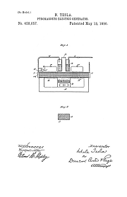
Pyromagneto-Electric Generator - May 26, 1887
Tesla's Arc-Light Technology
Automatic Lamps, Commutators, Regulators, DC Generator or "Dynamo"
To the Archive Page Discussion on Tesla's Technology
Lab-Tesla disclosures on the technology just presented
A NEW SYSTEM OF ALTERNATE CURRENT MOTORS AND TRANSFORMERS
Paper by Nikola Tesla read to the American Institute of Electrical Engineers on May 16, 1888
Tesla's Laboratory Power