335,787
ELECTRIC-ARC LAMP - July 13, 1885
UNITED STATES PATENT OFFICE
NIKOLA TESLA, OF SMILJAN LlKA, AUSTRIA-HUNGARY, ASSIGNOR TO THE TESLA ELECTRIC LIGHT AND MANUFACTURING COMPANY, OF RAHWAY, NEW JERSEY
Nikola Tesla Patent 335,787 ELECTRIC-ARC LAMP
SPECIFICATION forming part of Letters Patent No. 335,787, dated February 9,1886
Application filed July 13, 1885. Serial No. 171,416. (No model.)
To all whom it may concern:
Be it known that I, NIKOLA TESLA, of Smiljan Lika, border country of Austria-Hungary, have invented an Improvement in Electric-Arc Lamps, of which the following is a specification.
In another application, No. 160,574, filed by me March 30, 1885, I have shown and described a lamp having two magnets, in the main and shunt circuits, respectively, an armature-lever, and feed-mechanism connected to the armature-lever.
My present invention consists in some modifications of and improvements upon the devices shown in the application referred to.
In my present invention I further provide means for automatically withdrawing a lamp from the circuit, or cutting out the same, when, from a failure of the feed, the arc reaches an abnormal length, and also means for automatically reinserting such lamp in the circuit when the rod drops and the carbons come into contact.
My invention will be understood with reference to the accompanying drawings.
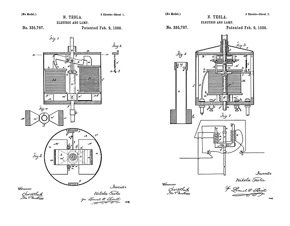
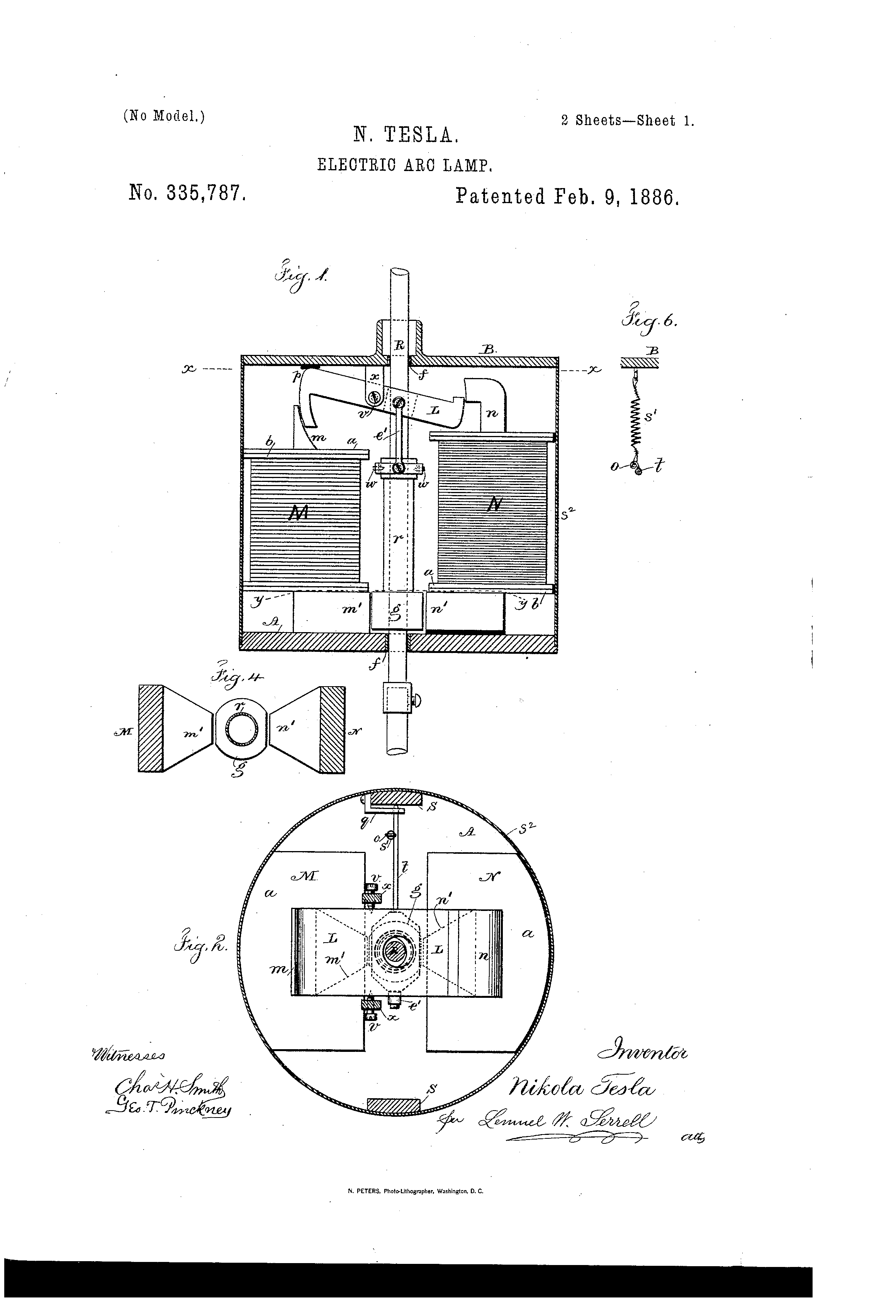
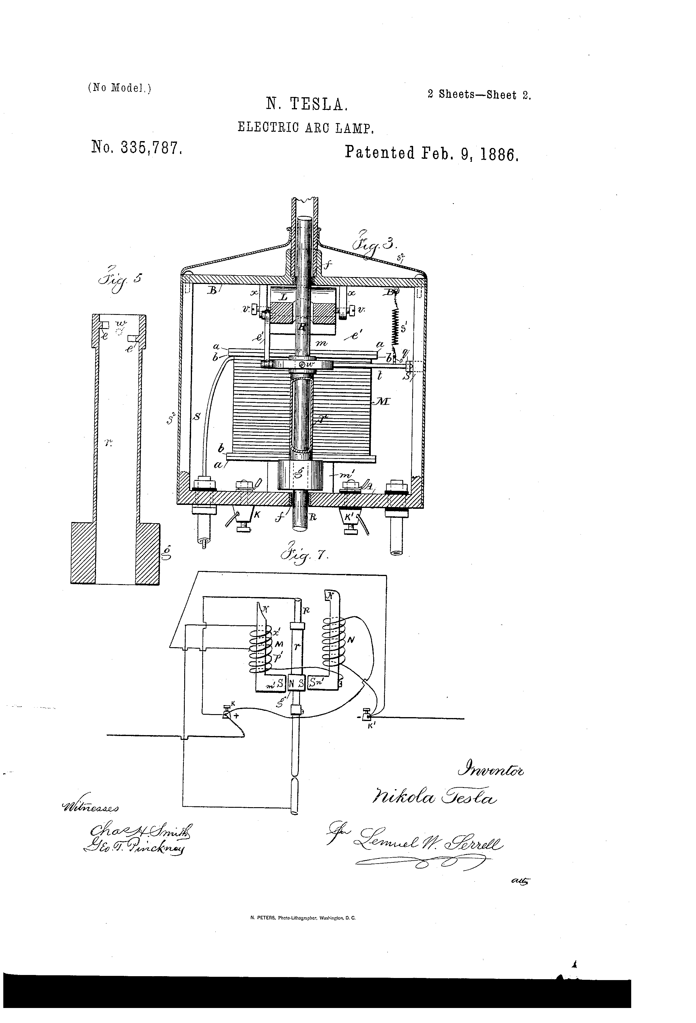
In the drawing, Figure 1 is an elevation of the lamp with the case in section. Fig. 2 is a sectional plan at the line x x. Fig. 3 is an elevation, partly in section, of the lamp at right angles to Fig. 1. Fig. 4 is a sectional plan at the line y y of Fig. 1. Fig 5 is a sectional of the clamp in about full size. Fig. 6 is a detached section illustrating the connection of the spring to the lever that carries the pivots of the clamp, and Fig. 7 is a diagram showing the circuit-connections of the lamp.
In the drawings, Fig. 1, M represents the main and N the shunt magnet, both securely fastened to the base A, which, with its side columns, S S, is preferably cast in one piece of brass or other diamagnetic material. To the magnet are soldered or otherwise fastened the brass washers or disks a a a a. Similar washers, b b, of fiber or other insulating material, serve to insulate the wires from the brass washers.
The magnets M and N are made very flat, so that their width exceeds three times their thickness, or even more. In this way a comparatively small number of convolutions is sufficient to produce the required magnetism, besides a greater surface is offered for cooling off the wires.
The upper pole-pieces, m n, of the magnets are curved, as indicated in the drawings, Fig. 1. The lower pole-pieces, m' n', are brought near together, tapering toward the armature g, as shown in Figs. 2 and 4. The object of this taper is to concentrate the greatest amount of the developed magnetism upon the armature, and also to allow the pull to be exerted always upon the middle of the armature g. This armature g is a piece of iron in the shape of a hollow cylinder, having on each side a segment cut away, the width of which is equal to the width of the pole-pieces m' n'.
The armature is soldered or otherwise fastened to the clamp r, which is formed of a brass tube, provided with gripping-jaws e e, Fig. 5. These jaws are arcs of a circle of the diameter of the rod R, and are made of some hard metal, preferably of hardened German silver. I also make the guides f f, through which the carbon-holding rod R slides, of the same material. This has the advantage to reduce greatly the wear and corrosion of the parts coming in frictional contact with the rod, which frequently causes trouble. The jaws e e are fastened to the inside of the tube r, so that one is a little lower than the other. The object of this is to provide a greater opening for the passage of the rod when the same is released by the clamp. The clamp r is supported on bearings w w, Figs. 1, 3 and 5, which are just in the middle between the jaws e e. I find this disposition to be the best. The bearings w w are carried by a lever, t, one end of which rests upon an adjustable support, q, of the side columns, S, the other end being connected by means of the link e' to the armature-lever L. The armature-lever L is a flat piece of iron in Z shape, having its ends curved so as to correspond to the form of the upper pole-pieces of the magnets M and N. It is hung upon the pivots v v, Fig. 2, which are in the jaw x of the top plate, B. This plate B, with the jaw, is preferably cast in one piece and screwed to the side columns, S S, that extend up from the base A. To partly balance the overweight of the moving parts a spring, s', Figs. 2 and 6, is fastened to the top plate, B, and hooked to the lever t. The hook o is toward one side of the lever or bent a little sidewise, as seen in Fig. 6. By this means a slight tendency is given to swing the armature toward the pole-piece m' of the main-magnet.
The binding-posts K K' are preferably screwed to the base A. A manual switch, for short-circuiting the lamp when the carbons are renewed, is also to be fastened to the base. This switch is of ordinary character, and is not shown in the drawings.
The rod R is electrically connected to the lamp-frame by means of a flexible conductor or otherwise. The lamp-case receives a removable ornamental cover, s2, around the same to inclose the parts.
The electrical connections are as indicated diagrammatically in Fig. 7.
The wire in the main magnet consists of two parts, x' and p'. These two parts may be in two separated coils or in one single helix, as shown in the drawings. The part x' being normally in circuit, is, with the fine wire upon the shunt-magnet, wound and traversed by the current in the same direction, so as to tend to produce similar poles, n n or s s, on the corresponding pole-pieces of the magnets M and N. The part p' is only in circuit when the lamp is cut out, and then the current being in the opposite direction produces in the main magnet magnetism of the opposite polarity.
The operation is as follows: At the start the carbons are to be in contact, and the current passes from the positive binding-post K to the lamp-frame, carbon-holder, upper and lower carbon, insulated return-wire in one of the side rods, and from there through the part x' of the wire on the main magnet to the negative binding-post. Upon the passage of the current the main magnet is energized and attracts the clamping-armature g, swinging the clamp and gripping the rod by means of the gripping-jaws e e. At the same time the armature-lever L is pulled down and the carbons separated. In pulling down the armature-lever L the main magnet is assisted by the shunt-magnet N, the latter being magnetized by magnetic induction from the magnet M.
It will be seen that the armatures L and g are practically the keepers for the magnets M and N, and owing to this fact both magnets with either one of the armatures L and g may be considered as one horseshoe-magnet, which we might term a “compound-magnet.” The whole of the soft-iron parts m, m', g, n', n, and L form a compound-magnet.
The carbons being separated, the fine wire receives a portion of the current. Now, the magnetic induction from the magnet M is such as to produce opposite poles on the corresponding ends of the magnet N; but the current traversing the helices tends to produce similar poles on the corresponding ends of both magnets, and therefore as soon as the fine wire is traversed by sufficient current the magnetism of the whole compound-magnet is diminished.
With regard to the armature g and operation of the lamp, the pole m' may be termed as the “clamping” and the pole n' as the “releasing” pole.
As the carbons burn away, the fine wire receives more current and the magnetism diminishes in proportion. This causes the armature-lever L to swing and the armature g to descend gradually under the weight of the moving parts until the end p, Fig. 1, strikes a stop on the top plate, B. The adjustment is such that when this takes place the rod R is yet gripped securely by the jaws e e. The further downward movement of the armature-lever being prevented, the arc becomes longer as the carbons are consumed, and the compound magnet is weakened more and more until the clamping-armature g releases the hold of the gripping-jaws e e upon the rod R, and the rod is allowed to drop a little, shortening thus the arc. The fine wire now receiving less current, the magnetism increases, and the rod is clamped again and slightly raised, if necessary. This clamping and releasing of the rod continues until the carbons are consumed. In practice the feed is so sensitive that for the greatest part of the time the movement of the rod cannot be detected without some actual measurement. During the normal operation of the lamp the armature-lever L remains stationary, or nearly so, in the position shown in Fig. 1.
Should it arise that, owing to an imperfection in the rod, the same and the carbons drop too far, so as to make the arc too short, or even bring the carbons in contact, then a very small amount of current passes through the fine wire, and the compound magnet becomes sufficiently strong to act as on the start in pulling the armature-lever L down and separating the carbons to a greater distance.
It occurs often in practice that the rod sticks in the guides. In this case the arc reaches a great length, until it finally breaks. Then the light goes out, and frequently the fine wire is injured. To prevent such an accident, I provide my lamp with an automatic cut-out. This cut-out operates as follows: When, upon a failure of the feed, the arc reaches a certain predetermined length, such an amount of current is diverted through the fine wire that the polarity of the compound magnet is reversed. The clamping-armature g is now moved against the shunt-magnet N until it strikes the releasing-pole n'. As soon as the contact is established, the current passes from the positive binding-post over the clamp r, armature g, insulated shunt-magnet, and the helix p' upon the main magnet M to the negative binding post. In this case the current passes in the opposite direction and changes the polarity of the magnet M, at the same time maintaining by magnetic induction in the core of the shunt-magnet the required magnetism without reversal of polarity, and the armature g remains against the shunt-magnet pole n'. The lamp is thus cut out as long as the carbons are separated. The cut-out may be used in this form without any further improvement; but I prefer to arrange it so that if the rod drops and the carbons come in contact the arc is started again. For this purpose I proportion the resistance of the part p' and the number of the convolutions of the wire upon the main magnet so that when the carbons come in contact a sufficient amount of current is diverted through the carbons and the part x' to destroy or neutralize the magnetism of the compound magnet. Then the armature g, having a slight tendency to approach to the clamping-pole m', comes out of contact with the releasing-pole n'. As soon as this happens, the current through the part p' is interrupted, and the whole current passes through the part x. The magnet M is now strongly magnetized, the armature g is attracted, and the rod clamped. At the same time the armature-lever L is pulled down out of its normal position and the arc started. In this way the lamp cuts itself out automatically when the arc gets so long, and reinserts itself automatically in the circuit if the carbons drop together.
It will be seen that the cut-out may be modified without departing from the spirit of my invention, as long as the shunt-magnet closes a circuit including a wire upon the main magnet and continues to keep the contact closed, being magnetized by magnetic induction from the main magnet. It is also obvious to say that the magnets and armatures may be of any desired shape.
I claim as my invention—
1. The combination, in an arc-lamp, of a main and a shunt magnet, an armature-lever to draw the arc, a clamp, and an armature to act upon the clamp, a clamping-pole and a releasing-pole upon the respective cores, the cores, poles, armature-lever, and clamping-armature forming a compound electro-magnet, substantially as set forth.
2. The combination, in an electric-arc lamp, of a carbon-holder and its rod, a clamp for such carbon-holder, a clamping-armature connected to the clamp, a compound electro-magnet controlling the action of the clamping-armature, and electric-circuit connections, substantially as set forth, for lessening the magnetism of the compound magnet when the arc between the carbons lengthens and augmenting the magnetism of the same when the arc is shortened, substantially as described.
3. The combination, with the carbon-holders in an electric lamp, of a clamp around the rod of the upper-carbon holder, the clamping-armature connected with said clamp, the armature-lever and connection from the same to the clamp, the main and shunt magnets, and the respective poles of the same to act upon the clamping-armature and armature-lever, respectively, substantially as set forth.
4. In an electric-arc lamp, a cut-out consisting of a main magnet, an armature, and a shunt-magnet having an insulated pole-piece, and the cut-out circuit-connections through the pole-piece and armature, substantially as set forth.
5. In an electric-arc lamp, the combination, with the carbon-holder and magnets, of the armatures L and g, link e', clamp r, and lever t, and the spring s', for the purpose set forth.
6. In an electric-arc lamp, the combination, with two upright magnets in the main and shunt circuits, respectively, having curved pole-pieces on one end and converging pole-pieces on the other end, of a flat z-shaped armature-lever between the curved pole-pieces and a clamping-armature between the convergent pole-pieces, substantially as described.
7. The combination, in an electric-arc lamp, of an electro-magnet in the main circuit and an electro-magnet in the shunt-circuit, an armature under the influence of the poles of the respective magnets, and circuit-connections controlled by such armature to cut out or shunt the lamp, substantially as specified, whereby the branch circuit is closed by the magnetism of the shunt-magnet, and then kept closed by induced magnetism from the main magnet, substantially as set forth.
8. The combination, with the carbon-holder and rod and the main and shunt magnets, of a feeding-clamp, an armature for the same, clamping and releasing poles upon the cores of the respective magnet, and circuit-connections through the clamping-armature, substantially as specified, for shunting the current when the electric arc between the carbons becomes abnormally long, substantially as set forth.
9. The combination, with the carbon-holding rod and a clamp for the same, of an armature upon the clamp, a shunt-magnet the pole of which acts to release the clamp, and a main magnet with a two-part helix, one portion being in the main circuit and the other portion in a shunt or cut-out circuit, the clamping-armature acting to close said cut-out circuit when the arc becomes too long and to break the shunt-circuit when the carbons come together, substantially as set forth.
Signed by me this 11th day of July, A.D. 1885.
NIKOLA TESLA
Source File: US Patent 335,787 - pdf
Chapter XL - The Martin Book
Nikola Tesla Direct Current Arc Lighting System
Thomas Commerford Martin
In a modification of [the previous] lamp, Mr. Tesla provided means for automatically withdrawing a lamp from the circuit, or cutting it out when, from a failure of the feed, the arc reached an abnormal length; and also means for automatically reinserting such lamp in the circuit when the rod drops and the carbons come into contact.
Fig. 283 is an elevation of the lamp with the case in section.
Fig. 284 is a sectional plan at the line x x.
Fig. 285 is an elevation, partly in section, of the lamp at right angles to Fig. 283. Fig. 286 is a sectional plan at the line y y of Fig. 283.
Fig. 287 is a section of the clamp in about full size. Fig. 288 is a detached section illustrating the connection of the spring to the lever that carries the pivots of the clamp, and Fig. 289 is a diagram showing the circuit-connections of the lamp.
In Fig. 283, M represents the main and N the shunt magnet, both securely fastened to the base A, which with its side columns, S S, are cast in one piece of brass or other diamagnetic material. To the magnets are soldered or otherwise fastened the brass washers or discs a a a a. Similar washers, b b, of fibre or other insulating material, serve to insulate the wires from the brass washers.
The magnets M and N are made very flat, so that their width exceeds three times their thickness, or even more. In this way a comparatively small number of convolutions is sufficient to produce the required magnetism, while a greater surface is offered for cooling off the wires.
The upper pole pieces, m n, of the magnets are curved, as indicated in the drawings, Fig. 283. The lower pole pieces m' n', are brought near together, tapering toward the armature g, as shown in Figs. 284 and 286. The object of this taper is to concentrate the greatest amount of the developed magnetism upon the armature, and also to allow the pull to be exerted always upon the middle of the armature g. This armature g is a piece of iron in the shape of a hollow cylinder, having on each side a segment cut away, the width of which is equal to the width of the pole pieces m' n'.
The armature is soldered or otherwise fastened to the clamp r, which is formed of a brass tube, provided with gripping-jaws e e, Fig. 287. These jaws are arcs of a circle of the diameter of the rod R, and are made of hardened German silver. The guides f f, through which the carbon-holding rod R slides, are made of the same material. This has the advantage of reducing greatly the wear and corrosion of the parts coming in frictional contact with the rod, which frequently causes trouble. The jaws e e are fastened to the inside of the tube r, so that one is a little lower than the other. The object of this is to provide a greater opening for the passage of the rod when the same is released by the clamp. The clamp r is supported on bearings w w, Figs. 283, 285 and 287, which are just in the middle between the jaws e e. The bearings w w are carried by a lever, t, one end of which rests upon an adjustable support, q, of the side columns, S, the other end being connected by means of the link e' to the armature-lever L. The armature-lever L is a flat piece of iron in N shape, having its ends curved so as to correspond to the form of the upper pole-pieces of the magnets M and N. It is hung upon the pivots v v, Fig. 284, which are in the jaw x of the top plate B. This plate B, with the jaw, is cast in one piece and screwed to the side columns, S S, that extend up from the base A. To partly balance the overweight of the moving parts, a spring, s', Figs. 284 and 288, is fastened to the top plate, B, and hooked to the lever t. The hook o is toward one side of the lever or bent a little sidewise, as seen in Fig. 288. By this means a slight tendency is given to swing the armature toward the pole-piece m' of the main magnet.
The binding-posts K K' are screwed to the base A. A manual switch, for short-circuiting the lamp when the carbons are renewed, is also fastened to the base. This switch is of ordinary character, and is not shown in the drawings.
The rod R is electrically connected to the lamp-frame by means of a flexible conductor or otherwise. The lamp-case receives a removable cover, s2, to inclose the parts.
The electrical connections are as indicated diagrammatically in Fig. 289. The wire in the main magnet consists of two parts, x' and p'. These two parts may be in two separated coils or in one single helix, as shown in the drawings. The part x' being normally in circuit, is, with the fine wire upon the shunt-magnet, wound and traversed by the current in the same direction, so as to tend to produce similar poles, N N or S S, on the corresponding pole-pieces of the magnets M and N. The part p' is only in circuit when the lamp is cut out, and then the current being in the opposite direction produces in the main magnet, magnetism of the opposite polarity.
The operation is as follows: At the start the carbons are to be in contact, and the current passes from the positive binding-post K to the lamp-frame, carbon-holder, upper and lower carbon, insulated return-wire in one of the side rods, and from there through the part x' of the wire on the main magnet to the negative binding-post. Upon the passage of the current the main magnet is energized and attracts the clamping-armature g, swinging the clamp and gripping the rod by means of the gripping jaws e e. At the same time the armature lever L is pulled down and the carbons are separated. In pulling down the armature lever L the main magnet is assisted by the shunt-magnet N, the latter being magnetized by magnetic induction from the magnet M.
It will be seen that the armatures L and g are practically the keepers for the magnets M and N, and owing to this fact both magnets with either one of the armatures L and g may be considered as one horseshoe magnet, which we might term a "compound magnet." The whole of the soft-iron parts M, m', g, n', N and L form a compound magnet.
The carbons being separated, the fine wire receives a portion of the current. Now, the magnetic induction from the magnet M is such as to produce opposite poles on the corresponding ends of the magnet N; but the current traversing the helices tends to produce similar poles on the corresponding ends of both magnets, and therefore as soon as the fine wire is traversed by sufficient current the magnetism of the whole compound magnet is diminished.
With regard to the armature g and the operation of the lamp, the pole m' may be considered as the "clamping" and the pole n' as the "releasing" pole.
As the carbons burn away, the fine wire receives more current and the magnetism diminishes in proportion. This causes the armature lever L to swing and the armature g to descend gradually under the weight of the moving parts until the end p, Fig. 283, strikes a stop on the top plate, B. The adjustment is such that when this takes place the rod R is yet gripped securely by the jaws e e. The further downward movement of the armature lever being prevented, the arc becomes longer as the carbons are consumed, and the compound magnet is weakened more and more until the clamping armature g releases the hold of the gripping-jaws e e upon the rod R, and the rod is allowed to drop a little, thus shortening the arc. The fine wire now receiving less current, the magnetism increases, and the rod is clamped again and slightly raised, if necessary. This clamping and releasing of the rod continues until the carbons are consumed. In practice the feed is so sensitive that for the greatest part of the time the movement of the rod cannot be detected without some actual measurement. During the normal operation of the lamp the armature lever L remains practically stationary, in the position shown in Fig. 283.
Should it happen that, owing to an imperfection in it, the rod and the carbons drop too far, so as to make the arc too short, or even bring the carbons in contact, a very small amount of current passes through the fine wire, and the compound magnet becomes sufficiently strong to act as at the start in pulling the armature lever L down and separating the carbons to a greater distance.
It occurs often in practical work that the rod sticks in the guides. In this case the are reaches a great length, until it finally breaks. Then the light goes out, and frequently the fine wire is injured. To prevent such an accident Mr. Tesla provides this lamp with an automatic cut-out which operates as follows: When, upon a failure of the feed, the arc reaches a certain predetermined length, such an amount of current is diverted through the fine wire that the polarity of the compound magnet is reversed. The clamping armature g is now moved against the shunt magnet N until it strikes the releasing pole n'. As soon as the contact is established, the current passes from the positive binding post over the clamp r, armature g, insulated shunt magnet, and the helix p' upon the main magnet M to the negative binding post. In this case the current passes in the opposite direction and changes the polarity of the magnet M, at the same time maintaining by magnetic induction in the core of the shunt magnet the required magnetism without reversal of polarity, and the armature g remains against the shunt magnet pole n'. The lamp is thus cut out as long as the carbons are separated. The cut out may be used in this form without any further improvement; but Mr. Tesla arranges it so that if the rod drops and the carbons come in contact the arc is started again. For this purpose he proportions the resistance of part p' and the number of the convolutions of the wire upon the main magnet so that when the carbons come in contact a sufficient amount of current is diverted through the carbons and the part x' to destroy or neutralize the magnetism of the compound magnet. Then the armature g, having a slight tendency to approach to the clamping pole m', comes out of contact with the releasing pole n'. As soon as this happens, the current through the part p' is interrupted, and the whole current passes through the part x. The magnet M is now strongly magnetized, the armature g is attracted, and the rod clamped. At the same time the armature lever L is pulled down out of its normal position and the arc started. In this way the lamp cuts itself out automatically when the arc gets too long, and reinserts itself automatically in the circuit if the carbons drop together.
Previous Chapter --- Contents --- Next Chapter
Related Patent
335,786
Electric-Arc Lamp - March 30, 1885
Tesla's Arc-Light Technology
Automatic Lamps, Commutators, Regulators, DC Generator or "Dynamo"
To the Archive Page Discussion on Tesla's Technology

Lab-Tesla disclosures on the technology just presented
A NEW SYSTEM OF ALTERNATE CURRENT MOTORS AND TRANSFORMERS
Paper by Nikola Tesla read to the American Institute of Electrical Engineers on May 16, 1888
EXPERIMENTS WITH ALTERNATE CURRENTS OF VERY HIGH FREQUENCY AND THEIR APPLICATION TO METHODS OF ARTIFICIAL ILLUMINATION