406,968
DYNAMO-ELECTRIC MACHINE - March 23, 1889
UNITED STATES PATENT OFFICE
NIKOLA TESLA, OF NEW YORK, N. Y., ASSIGNOR OF TWO-THIRDS TO CHARLES F. PECK, OF ENGLEWOOD, NEW JERSEY, AND ALFRED S. BROWN, OF NEW YORK, N. Y.
Nikola Tesla Patent 406,968 DYNAMO-ELECTRIC MACHINE
SPECIFICATION forming part of Letters Patent No. 406,968, dated July 16, 1889.
Application filed March 23, 1889. Serial No. 304,498. (No model.)
To all whom it may concern:
Be it known that I, NIKOLA TESLAfrom Smiljan, Lika, border country of Austria-Hungary, a subject of the Emperor of Austria, and a resident of New York, in the county and State of New York, have invented certain new and useful Improvements in Dynamo or Magneto Electric Machines, of which the following is a specification, reference being had to the accompanying drawings.
This invention relates to that class of electrical generators known as “unipolar,” in which a disk or cylindrical conductor is mounted between magnetic poles adapted to produce an approximately-uniform field. In the first-named or disk armature machines the currents induced in the rotating conductor flow from the center to periphery, or conversely, according to the direction of rotation or the lines of force as determined by the signs of the magnetic poles, and these currents are taken off usually by connections or brushes applied to the disk at points on its periphery and near its center. In the case of the cylindrical armature-machine the currents developed in the cylinder are taken off by brushes applied to the sides of the cylinder at its ends.
In order to develop economically an electro-motive force available for practicable purposes, it is necessary either to rotate the conductor at a very high rate of speed or to use a disk of large diameter or cylinder of great length; but in either case it becomes difficult to secure and maintain a good electrical connection between the collecting-brushes and the conductor, owing to the high peripheral speed.
It has been proposed to couple two or more disks together in series with the object of obtaining a higher electro-motive force; but with the connections heretofore used and using other conditions of speed and dimension of disk necessary to securing good practicable results this difficulty is still felt to be a serious obstacle to the use of this kind of generator. These objections I have sought to avoid; and for this purpose I construct a machine with two fields, each having a rotary conductor mounted between its poles, but the same principle is involved in the case of both forms of machine above described, and as I prefer to use the disk form I shall confine the description herein to that machine. The disks are formed with flanges, after the manner of pulleys, and are connected together by flexible conducting bands or belts.
I prefer to construct the machine in such manner that the direction of magnetism or order of the poles in one field of force is opposite to that in the other, so that rotation of the disks in the same direction develops a current in one from center to circumference and in the other from circumference to center. Contacts applied therefore to the shafts upon which the disks are mounted form the terminals of a circuit the electro-motive force in which is the sum of the electro-motive forces of the two disks.
I would call attention to the obvious fact that if the direction of magnetism in both fields be the same the same result as above will be obtained by driving the disks in opposite directions and crossing the connecting-belts. In this way the difficulty of securing and maintaining good contact with the peripheries of the disks is avoided and a cheap and durable machine made which is useful for many purposes—such as for an exciter for alternating-current generators, for a motor, and for any other purpose for which dynamo-machines are used.
The specific construction of the machine which I have just generally described I have illustrated in the accompanying drawings, in which—
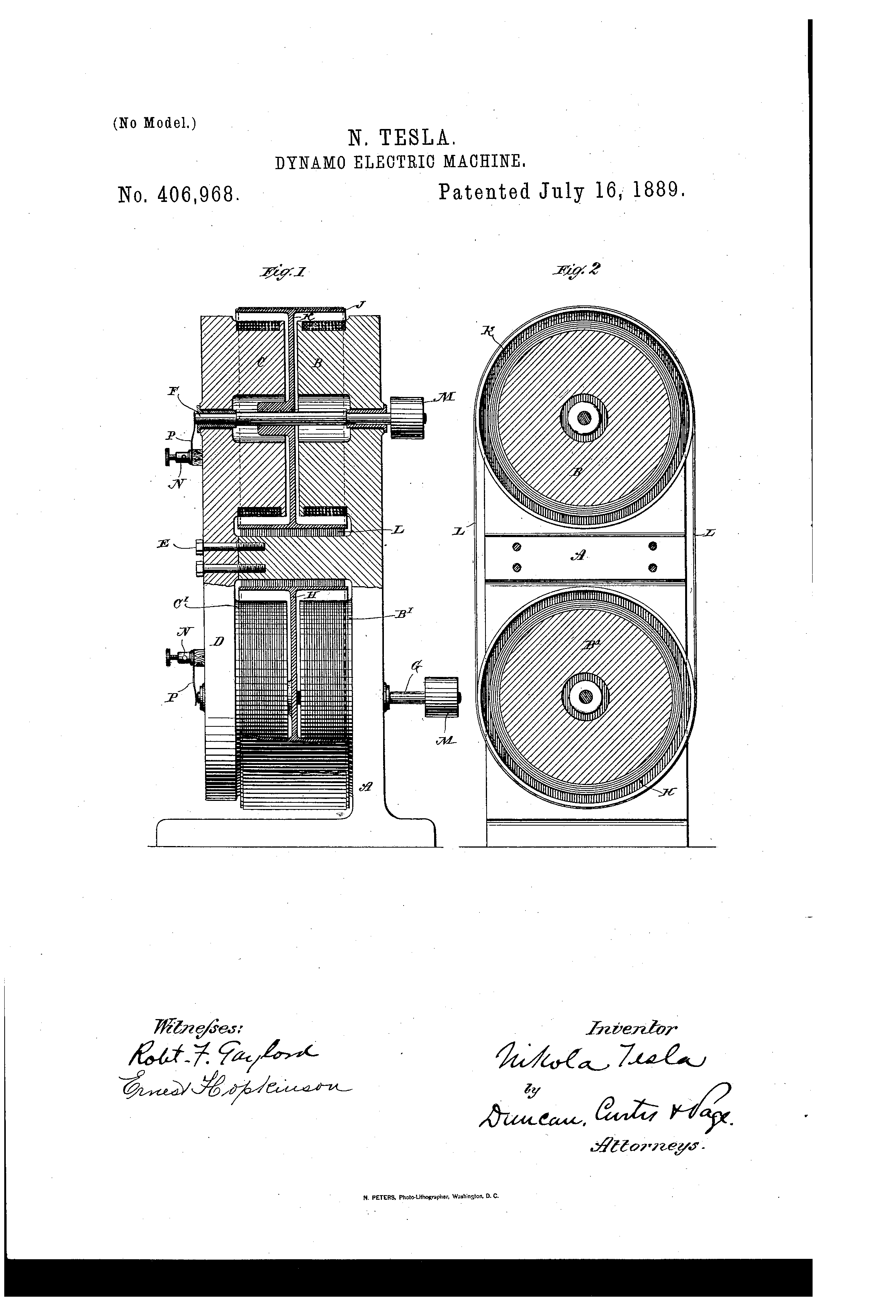
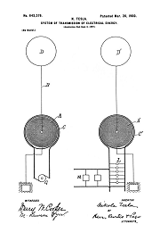
Figure 1 is a side view, partly in section, of my improved machine. Fig. 2 is a vertical section of the same at right angles to the shafts.
In order to form a frame with two fields of force, I cast a support A with two pole-pieces B B' integral with it. To this I join by bolts E a casting D, with two similar and corresponding pole-pieces C C'. The pole-pieces B B' are wound or connected to produce a field of force of given polarity, and the pole-pieces C C' are wound or connected to produce a field of opposite polarity. The driving-shafts F G pass through the poles and are journaled in insulating-bearings in the casting A D, as shown.
H K are the disks or generating-conductors. They are composed of copper, brass, or iron and are keyed or secured to their respective shafts. They are provided with broad peripheral flanges J. It is of course obvious that the disks may be insulated from their shafts, if so desired. A flexible metallic belt L is passed over the flanges of the two disks, and, if desired, may be used to drive one of the disks. I prefer, however, to use this belt merely as a conductor, and for this purpose may use sheet steel, copper, or other suitable metal. Each shaft is provided with a driving-pulley M, by which power is imparted from a counter-shaft.
N N are the terminals. For sake of clearness they are shown as provided with springs P, that bear upon the ends of the shafts. This machine, if self-exciting, would have copper bands around its poles, or conductors of any kind—such as the wires shown in the drawings—may be used.
I do not limit my invention to the special construction herein shown. For example, it is not necessary that the parts be constructed in one machine or that the materials and proportions herein given be strictly followed. Furthermore, it is evident that the conducting belt or band may be composed of several smaller bands and that the principle of connection herein described may be applied to more than two machines.
What I claim is—
1. An electrical generator consisting of the combination, with two rotary conductors mounted in unipolar fields, of a flexible conductor or belt passing around the peripheries of said conductors, as herein set forth.
2. The combination, with two rotary conducting-disks having peripheral flanges and mounted in unipolar fields, of a flexible conducting belt or band passing around the flanges of both disks, as set forth.
3. The combination of independent sets of field-magnets adapted to maintain unipolar fields, conducting-disks mounted to rotate in said fields, independent driving mechanism for each disk, and a flexible conducting belt or band passing around the peripheries of the disks, as set forth.
NIKOLA TESLA
Click image for higher-resolution
Source File: US Patent 406,968 - pdf
This is an important patent and is discussed Here & Here & Here.
Chapter XLI - The Martin Book
Thomas Commerford Martin
Improvement in "Unipolar" Generators
Another interesting class of apparatus to which Mr Tesla has directed his attention is that of "unipolar" generators in which a disc or a cylindrical conductor is mounted between magnetic poles adapted to produce an approximately uniform field. In the disc armature machines the currents induced in the rotating conductor flow from the centre to the periphery, or conversely. according to the direction of rotation or the lines of force as determined by the signs of the magnetic poles, and these currents are taken off usually by connections or brushes applied to the disc at points on its periphery and near its centre. In the case of the cylindrical armature machine the currents developed in the cylinder are taken off by brushes applied to the sides of the cylinder at its ends.
In order to develop economically an electromotive force available for practicable purposes, it is necessary either to rotate the conductor at a very high rate of speed or to use a disc of large diameter or a cylinder of great length; but in either case it becomes difficult to secure and maintain a good electrical connection between the collecting brushes and the conductor. owing to the high peripheral speed.
It has been proposed to couple two or more discs together in series, with the object of obtaining a higher electro-motive force; but with the connections heretofore used and using other conditions of speed and dimension of disc necessary to securing good practicable results this difficulty is still felt to be a serious obstacle to the use of this kind of generator. These objections Mr Tesla has sought to avoid by constructing a machine with two fields each having a rotary conductor mounted between its poles. The same principle is involved in the case of both forms of machine above described, but the description now given is confined to the disc type, which Mr Tesla is inclined to favor for that machine. The discs are formed with flanges, after the manner of pulleys, and are connected together by flexible conducting bands or belts.
The machine is built in such manner that the direction of magnetism or order of the poles in one field of force is opposite to that in the other, so that rotation of the discs in the same direction develops a current in one from centre to circumference and in the other from circumference to centre. Contacts applied therefore to the shafts upon which the discs are mounted form the terminals of a circuit the electro-motive force in which is the sum of the electro-motive forces of the two dises.
It will be obvious that if the direction of magnetism in both fields be the same, the same result as above will be obtained by driving the discs in opposite directions and crossing the connecting belts. In this way the difficulty of securing and maintaining good contact with the peripheries of the discs is avoided and a cheap and durable machine made which is useful for many purposes -- such as for an exciter for alternating current generators, for a motor, and for any other purpose for which dynamo machines are used.
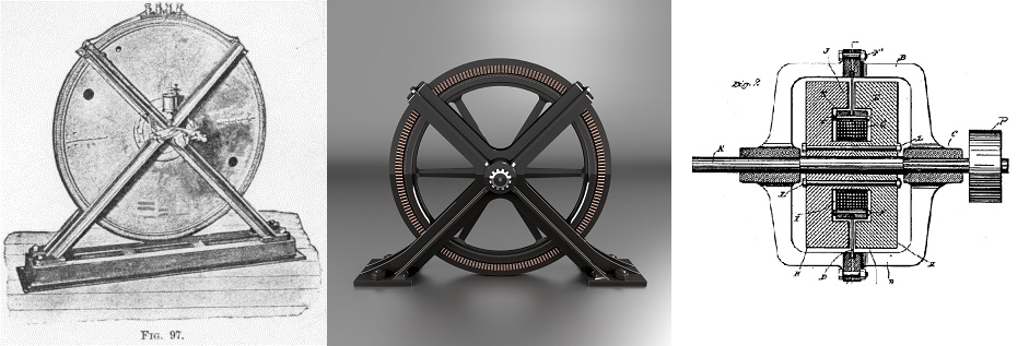
Fig 290 is a side view, partly in section, of this machine Fig 291 is a vertical section of the same at right angles to the shafts.
In order to form a frame with two fields of force, a support, A, is cast with two pole pieces B B' integral with it. To this are joined by bolts E a casting D, with two similar and corresponding pole pieces C C'. The pole pieces B B' are wound and connected to produce a field of force of given polarity, and the pole pieces C C' are wound so as to produce a field of opposite polarity. The driving shafts F G pass through the poles and are journaled in insulating bearings in the casting A D as shown.
H K are the discs or generating conductors. They are composed of copper, brass, or iron and are keyed or secured to their respective shafts. They are provided with broad peripheral flanges J. It is of course obvious that the discs may be insulated from their shafts, if so desired. A flexible metallic belt L is passed over the flanges of the two discs, and, if desired, may be used to drive one of the discs. It is better, however, to use this belt merely as a conductor, and for this purpose sheet steel, copper, or other suitable metal is used. Each shaft is provided with a driving pulley M, by which power is imparted from a driving shaft.
N N are the terminals. For the sake of clearness they are shown as provided with springs P, that bear upon the ends of the shafts. This machine, if self exciting, would have copper bands around its poles; or conductors of any kind -- such as wires shown in the drawings -- may be used.
Notes on a Unipolar Dynamo
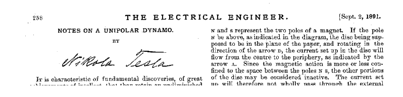
Article by Nikola Tesla, The Electrical Engineer, September 2, 1891, Vol. XII.
It is characteristic of fundamental discoveries, of great achievements of intellect, that they retain an undiminished power upon the imagination of the thinker. The memorable experiment of Faraday with a disc rotating between the two poles of a magnet, which has borne such magnificent fruit, has long passed into every-day experience; yet there are certain features about this embryo of the present dynamos and motors which even to-day appear to us striking, and are worthy of the most careful study.
Consider, for instance, the case of a disc of iron or other metal revolving between the two opposite poles of a magnet, and the polar surfaces completely covering both sides of the disc, and assume the current to be taken off or conveyed to the same by contacts uniformly from all points of the periphery of the disc. Take first the case of a motor. In all ordinary motors the operation is dependent upon some shifting or change of the resultant of the magnetic attraction exerted upon the armature, this process being effected either by some mechanical contrivance on the motor or by the action of currents of the proper character. We may explain the operation of such a motor just as we can that of a water-wheel. But in the above example of the disc surrounded completely by the polar surfaces, there is no shifting of the magnetic action, no change whatever, as far as we know, and yet rotation ensues. Here, then, ordinary considerations do not apply; we cannot even give a superficial explanation, as in ordinary motors, and the operation will be clear to us only when we shall have recognized the very nature of the forces concerned, and fathomed the mystery of the invisible connecting mechanism.
Considered as a dynamo machine, the disc is an equally interesting object of study. In addition to its peculiarity of giving currents of one direction without the employment of commutating devices, such a machine differs from ordinary dynamos in that there is no reaction between armature and field. The armature current tends to set up a magnetization at right angles to that of the field current, but since the current is taken off uniformly from all points of the periphery, and since, to be exact, the external circuit may also be arranged perfectly symmetrical to the field magnet, no reaction can occur. This, however, is true only as long as the magnets are weakly energized, for when the magnets are more or less saturated, both magnetizations at right angles seemingly interfere with each other.
For the above reason alone it would appear that the output of such a machine should, for the same weight, be much greater than that of any other machine in which the armature current tends to demagnetize the field. The extraordinary output of the Forbes unipolar dynamo and the experience of the writer confirm this view.
Again, the facility with which such a machine may be made to excite itself is striking, but this may be due—besides to the absence of armature reaction—to the perfect smoothness of the current and non-existence of self-induction.
If the poles do not cover the disc completely on both sides, then, of course, unless the disc be properly subdivided, the machine will be very inefficient. Again, in this case there are points worthy of notice. If the disc be rotated and the field current interrupted, the current through the armature will continue to flow and the field magnets will lose their strength comparatively slowly. The reason for this will at once appear when we consider the direction of the currents set up in the disc.
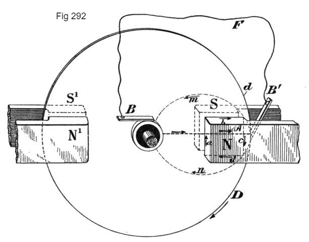
Referring to the diagram Fig. 292, d represents the disc with the sliding contacts B B' on the shaft and periphery. N and S represent the two poles of a magnet. If the pole N be above, as indicated in the diagram, the disc being supposed to be in the plane of the paper, and rotating in the direction of the arrow D, the current set up in the disc will flow from the centre to the periphery, as indicated by the arrow A. Since the magnetic action is more or less confined to the space between the poles N S, the other portions of the disc may be considered inactive. The current set up will therefore not wholly pass through the external circuit F, but will close through the disc itself, and generally, if the disposition be in any way similar to the one illustrated, by far the greater portion of the current generated will not appear externally, as the circuit F is practically short-circuited by the inactive portions of the disc. The direction of the resulting currents in the latter may be assumed to be as indicated by the dotted lines and arrows m and n; and the direction of the energizing field current being indicated by the arrows a b c d, an inspection of the figure shows that one of the two branches of the eddy current, that is, A B' m B, will tend to demagnetize the field, while the other branch, that is, A B' n B, will have the opposite effect. Therefore, the branch A B' m B, that is, the one which is approaching the field, will repel the lines of the same, while branch A B' n B, that is, the one leaving the field, will gather the lines of force upon itself.
In consequence of this there will be a constant tendency to reduce the current flow in the path A B' m B, while on the other hand no such opposition will exist in path A B' n B, and the effect of the latter branch or path will be more or less preponderating over that of the former. The joint effect of both the assumed branch currents might be represented by that of one single current of the same direction as that energizing the field. In other words, the eddy currents circulating in the disc will energize the field magnet. This is a result quite contrary to what we might be led to suppose at first, for we would naturally expect that the resulting effect of the armature currents would be such as to oppose the field current, as generally occurs when a primary and secondary conductor are placed in inductive relations to each other. But it must be remembered that this results from the peculiar disposition in this case, namely, two paths being afforded to the current, and the latter selecting that path which offers the least opposition to its flow. From this we see that the eddy currents flowing in the disc partly energize the field, and for this reason when the field current is interrupted the currents in the disc will continue to flow, and the field magnet will lose its strength with comparative slowness and may even retain a certain strength as long as the rotation of the disc is continued.
The result will, of course, largely depend on the resistance and geometrical dimensions of the path of the resulting eddy current and on the speed of rotation; these elements, namely, determine the retardation of this current and its position relative to the field. For a certain speed there would be a maximum energizing action; then at higher speeds, it would gradually fall off to zero and finally reverse, that is, the resultant eddy current effect would be to weaken the field. The reaction would be best demonstrated experimentally by arranging the fields N S, N' S', freely movable on an axis concentric with the shaft of the disc. If the latter were rotated as before in the direction of the arrow D, the field would be dragged in the same direction with a torque, which, up to a certain point, would go on increasing with the speed of rotation, then fall off, and, passing through zero, finally become negative; that is, the field would begin to rotate in opposite direction to the disc. In experiments with alternate current motors in which the field was shifted by currents of differing phase, this interesting result was observed. For very low speeds of rotation of the field the motor would show a torque of 900 lbs. or more, measured on a pulley 12 inches in diameter. When the speed of rotation of the poles was increased, the torque would diminish, would finally go down to zero, become negative, and then the armature would begin to rotate in opposite direction to the field.
To return to the principal subject; assume the conditions to be such that the eddy currents generated by the rotation of the disc strengthen the field, and suppose the latter gradually removed while the disc is kept rotating at an increased rate. The current, once started, may then be sufficient to maintain itself and even increase in strength, and then we have the case of Sir William Thomson's "current accumulator." But from the above considerations it would seem that for the success of the experiment the employment of a disc not subdivided would be essential, for if there should be a radial subdivision, the eddy currents could not form and the self-exciting action would cease. If such a radially subdivided disc were used it would be necessary to connect the spokes by a conducting rim or in any proper manner so as to form a symmetrical system of closed circuits.
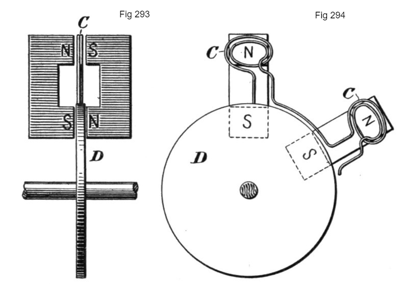
The action of the eddy currents may be utilized to excite a machine of any construction. For instance, in Figs. 293 and 294 an arrangement is shown by which a machine with a disc armature might be excited. Here a number of magnets, N S, N S, are placed radially on each side of a metal disc D carrying on its rim a set of insulated coils, C C. The magnets form two separate fields, an internal and an external one, the solid disc rotating in the field nearest the axis, and the coils in the field further from it. Assume the magnets slightly energized at the start; they could be strengthened by the action of the eddy currents in the solid disc so as to afford a stronger field for the peripheral coils. Although there is no doubt that under proper conditions a machine might be excited in this or a similar manner, there being sufficient experimental evidence to warrant such an assertion, such a mode of excitation would be wasteful.
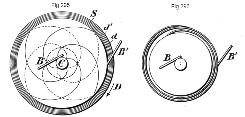
But a unipolar dynamo or motor, such as shown in Fig. 292, may be excited in an efficient manner by simply properly subdividing the disc or cylinder in which the currents are set up, and it is practicable to do away with the field coils which are usually employed. Such a plan is illustrated in Fig. 295. The disc or cylinder D is supposed to be arranged to rotate between the two poles N and S of a magnet, which completely cover it on both sides, the contours of the disc and poles being represented by the circles d and d1 respectively, the upper pole being omitted for the sake of clearness. The cores of the magnet are supposed to be hollow, the shaft C of the disc passing through them. If the unmarked pole be below, and the disc be rotated screw fashion, the current will be, as before, from the centre to the periphery, and may be taken off by suitable sliding contacts, B B', on the shaft and periphery respectively. In this arrangement the current flowing through the disc and external circuit will have no appreciable effect on the field magnet.
The result will, of course, largely depend on the resistance and geometrical dimensions of the path of the resulting eddy current and on the speed of rotation; these elements, namely, determine the retardation of this current and its position relative to the field. For a certain speed there would be a maximum energizing action: then at higher speeds, it would gradually fall off to zero and finally reverse, that is, the resultant eddy current effect would be to weaken the field. The reaction would be best demonstrated experimentally by arranging the fields N S, N' S', freely movable on an axis concentric with the shaft of the disc. If the latter were rotated as before in the direction of the arrow D, the field would be dragged in the same direction with a torque, which, up to a certain point, would go on increasing with the speed of rotation, then fall off, and, passing through zero, finally become negative; that is, the field would begin to rotate in opposite direction to the disc. In experiments with alternate current motors in which the field was shifted by currents of differing phase, this interesting result was observed. For very low speeds of rotation of the field the motor would show a torque of 900 lbs. or more, measured on a, pulley 12 inches in diameter. When the speed of rotation of the poles was increased, the torque would diminish, would finally go down to zero, become negative, and then the armature would begin to rotate in opposite direction to the field-To return to the principal subject; assume the conditions to be such that the eddy currents generated by the rotation of the disc strengthen the field, and suppose the latter gradually removed while the disc is kept rotating at an increased rate. The current, once started, may then be sufficient to maintain itself and even increase in strength, and then we have the case of Sir William Thomson's "current accumulator".
But from the above considerations it would seem that for the success of the experiment the employment of a disc not subdivided would be essential, for if there should be a radial subdivision, the eddy currents could not form and the self-exciting action would cease. If such a radially subdivided disc were used it would be necessary to connect the spokes by a conducting rim or in any proper manner so as to form a symmetrical system of closed circuits.
The action of the eddy currents may be utilized to excite a machine of any construction. For instance, in Figs. 2 and 3 an arrangement is shown by which a machine with a disc armature might be excited. Here a number of magnets, N S, N S, are placed radially on each side of a metal disc D carrying on its rim a. set of insulated coils, C C The magnets form two separate fields, an internal and an external one, the solid disc rotating in the field nearest the axis, and the coils in the field further from it-Assume the magnets slightly energized at the start; they could be strengthened by the action of the eddy currents in the solid disc so as to afford a stronger field for the peripheral coils. Although there is no doubt that under proper conditions a machine might be excited in this or a similar manner, there being sufficient experimental evidence to warrant such an assertion, such a mode of excitation would be wasteful.
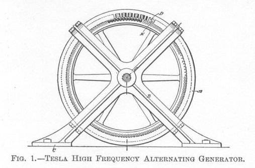
But an unipolar dynamo or motor, such as shown in Fig, 1 may be excited in an efficient manner by simply properly subdividing the disc or cylinder in which the currents are set up, and it is practicable to do away with the field coils which are usually employed. Such a plan is illustrated in Fig. 4. The disc or cylinder D is supposed to be arranged to rotate between the two poles N and S of a magnet, which completely cover it on both sides, the contours of the disc and poles being represented by the circles d and d' respectively, the upper pole being omitted for the sake of clearness.
The cores of the magnet are supposed to be hollow, the shaft C of the disc passing through them. If the unmarked pole be below, and the disc be rotated screw fashion, the current will be, as before, from the centre to the periphery, and may be taken off by suitable sliding contacts, B B', on the shaft and periphery respectively. In this arrangement the current flowing through the disc and external circuit will have no appreciable effect on the field magnet.
But let us now suppose the disc to be subdivided, spirally, as indicated by the full or dotted lines. Fig. 295. The difference of potential between a point on the shaft and a point on the periphery wilt remain unchanged, in sign as well as in amount. The only difference will be that the resistance of the disc will be augmented and that there will be a greater fall of potential from a point on the shaft to a point on the periphery when the same current is traversing the external circuit. But since the current is forced to follow the lines of subdivision, we see that it will tend either to energize or de-energize the field, and this will depend, other things being equal, upon the direction of the Lines of subdivision. If the subdivision be as indicated by the full lines in Fig, 4, it is evident that if the current is of the same direction as before, that is, from centre to periphery, its effect will be to strengthen the field magnet; whereas, if the subdivision be as indicated by the dotted lines, the current generated will tend to weaken the magnet. In the former case the machine will be capable of exciting itself when the disc is rotated in the direction of arrow D; in the latter case the direction of rotation must be reversed. Two such discs may be combined, however, as indicated, the two discs rotating in opposite fields, and in the same or opposite direction.
Similar disposition may, of course, be made in a type of machine in which, instead of a disc, a cylinder is rotated. In such unipolar machines, in the manner indicated, the usual field coils and poles may be omitted and the machine may be made to consist only of a cylinder or of two discs enveloped by a metal casting.
Instead of subdividing the disc or cylinder spirally, as indicated in Fig. 295, it is more convenient to interpose one or more turns between the disc and the contact ring on the periphery, as illustrated in Fig. 296.
A Forbes dynamo may, for instance, be excited in such a manner. In the experience of the writer it has been found that instead of taking the current from two such discs by sliding contacts, as usual, a flexible conducting belt may be employed to advantage. The discs are in such case provided with large flanges, affording a very great contact surface. The belt should be made to beat on the flanges with spring pressure to take up the expansion. Several machines with belt contact were constructed by the writer two years ago, and worked satisfactorily; but for want of time the work in that direction has been temporarily suspended. A number of features, pointed out above have also been used by the writer in connection with some types of alternating current motors.
Nikola Tesla, 1891
Previous Chapter --- Contents --- Next Chapter
To the Archive Page Discussion on Tesla's Technology

Lab-Tesla disclosures on the technology just presented
Tesla Transmitters
Wireless Transmission of Electrical Energy
Tesla's Cymatic Research
Steam Powered Isochronous Acoustic Oscillators & Generators
Self-Exciting Dynamos and Alternators
Rectification, Energy Conversion
EXPERIMENTS WITH ALTERNATE CURRENTS OF VERY HIGH FREQUENCY AND THEIR APPLICATION TO METHODS OF ARTIFICIAL ILLUMINATION