359,748
DYNAMO-ELECTRIC MACHINE - January 14, 1886
UNITED STATES PATENT OFFICE
NIKOLA TESLA, OF SMILJAN LIKA, AUSTRIA-HUNGARY, ASSIGNOR TO THE TESLA ELECTRIC LIGHT AND MANUFACTURING COMPANY, OF RAHWAY, NEW JERSEY.
Nikola Tesla Patent 359,748 DYNAMO-ELECTRIC MACHINE
SPECIFICATION forming part of Letters Patent No. 359,748, dated March 22, 1887
Application filed January 14, 1886. Renewed December 1, 1886. Serial No. 220,370. (No model.)
To all whom it may concern:
Be it known that I, NIKOLA TESLA, of Smiljan Lika, border country of Austria-Hungary, have invented an Improvement in Dynamo-Electric Machines, of which the following is a specification.
The main objects of my invention are to increase the efficiency of the machine and to facilitate and cheapen the construction of the same; and to this end my invention relates to the magnetic frame and the armature, and to other features of construction, hereinafter more fully explained.
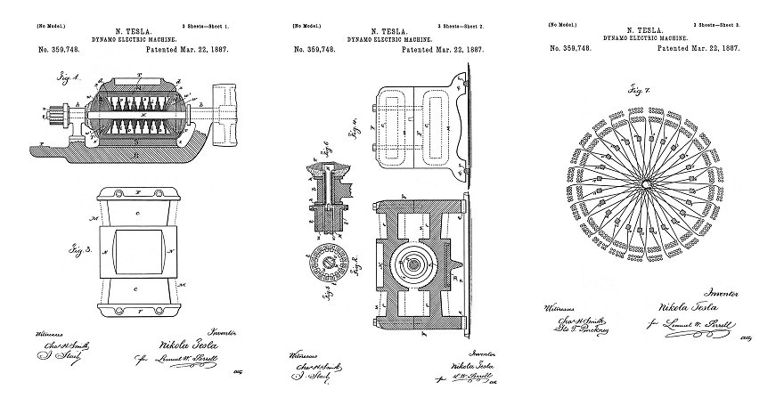
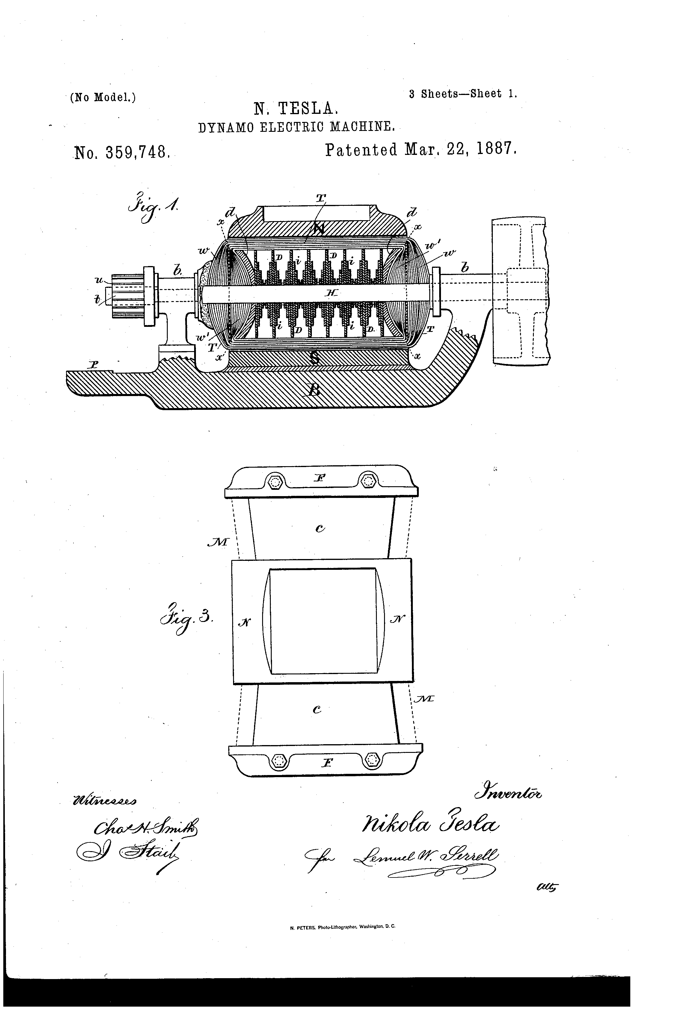
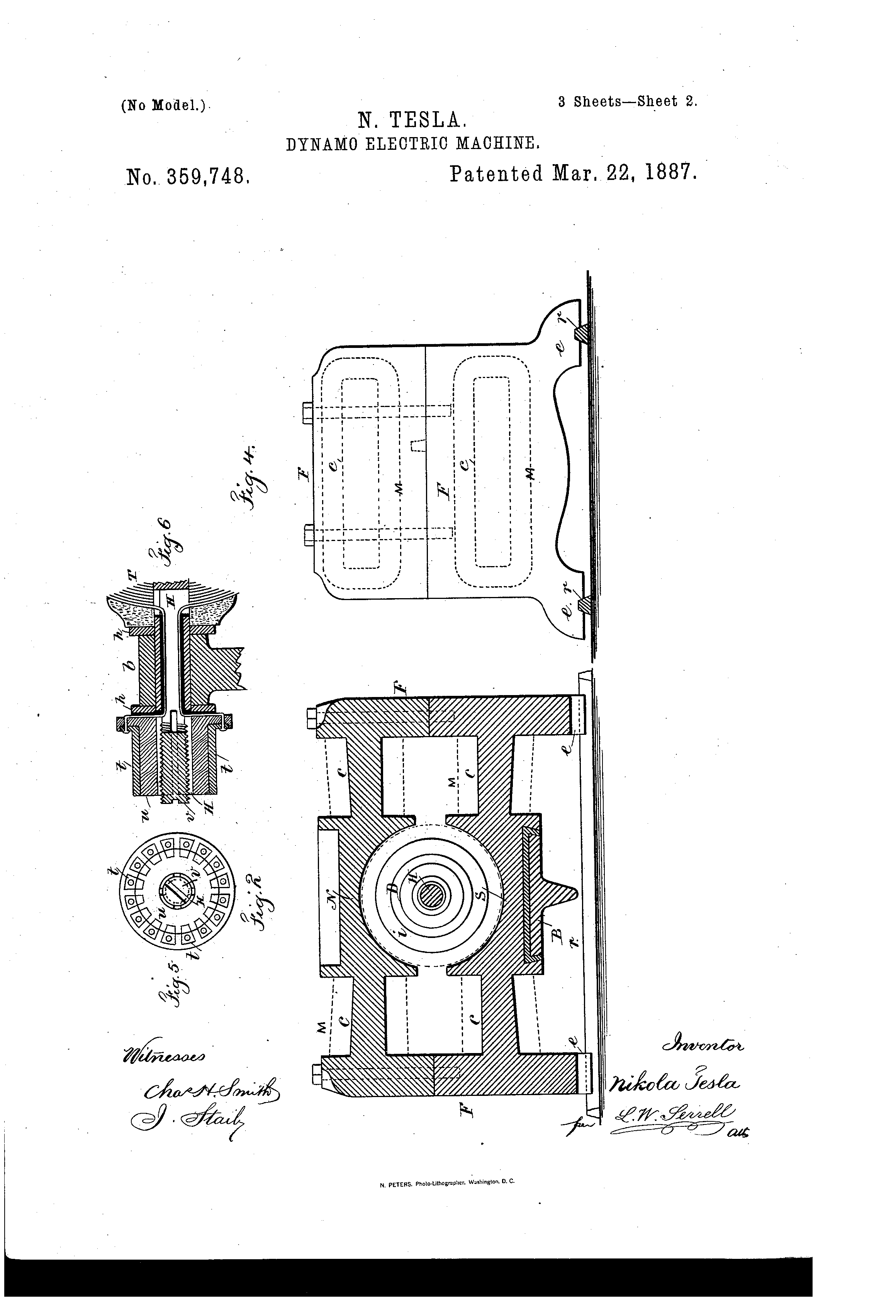
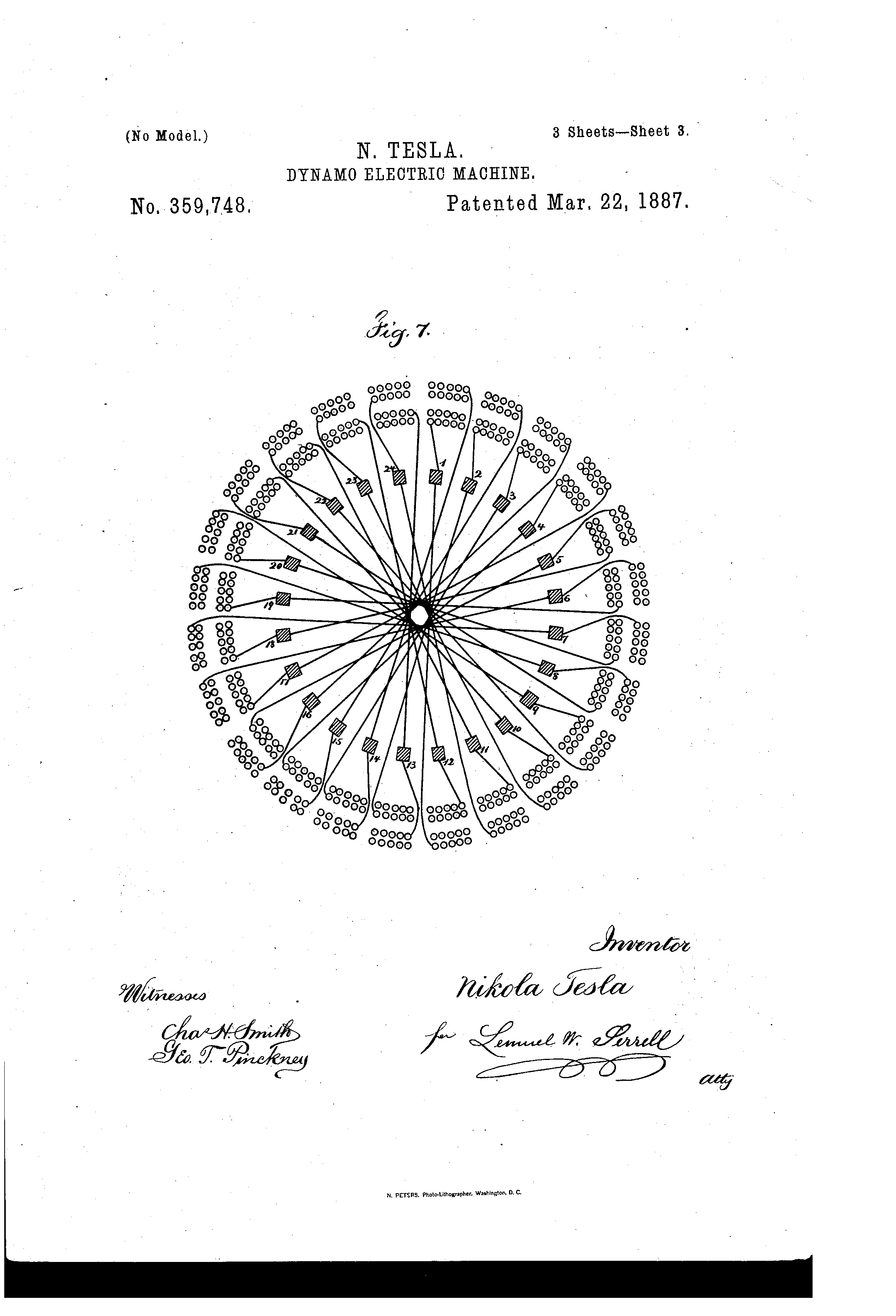
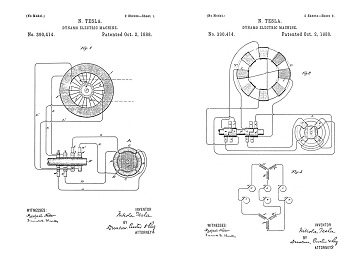
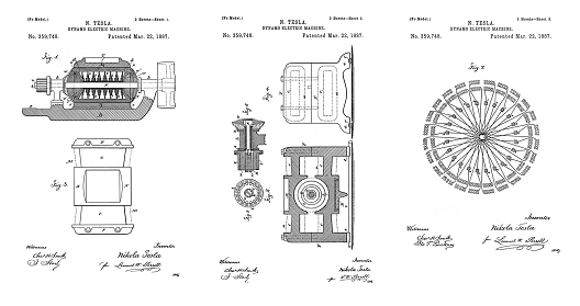
My invention is illustrated in the accompanying drawings, in which Figure 1 is a longitudinal section, and Fig. 2 a cross-section, of the machine. Fig. 3 is a top view, and Fig. 4 a side view, of the magnetic frame. Fig. 5 is an end view of the commutator-bars, and Fig. 6 is a section of the shaft and commutator-bars. Fig. 7 is a diagram illustrating the coils of the armature and the connections to the commutator-plates.
The cores c c c c of the field-magnets may be tapering in both directions, as shown, for the purposes of concentrating the magnetism upon the middle of the pole-pieces.
The connecting-frame F F of the field-magnets is in the form indicated in the side view, Fig. 4, the lower part being provided with the spreading curved cast legs e e, so that the machine will rest firmly upon two base-bars, r r.
To the lower pole, S, of the field-magnet M is fastened, preferably by means of Babbit or other fusible diamagnetic material, the base B, which is provided with bearings b for the armature-shaft H. The base B has a projection, P, which supports the brush-holders and regulating devices, which may be such as shown in an application of like date herewith.
The armature is constructed with the view to reduce to a minimum the loss of power due to the transversal or Foucault currents and to the change of polarity, and also to shorten as much as possible the length of the inactive wire wound upon the armature-core.
It is well known that when the armature is revolved between the poles of the field-magnets currents are generated in the iron body of the armature which develop heat, and consequently cause a waste of power. Owing to the mutual action of the lines of force, the magnetic properties of iron, and the speed of the different portions of the armature-core, these currents are generated principally on and near the surface of the armature-core, diminishing in strength gradually toward the center of the core. Their quantity is under same conditions proportional to the length of the iron body in the direction in which these currents are generated. By subdividing the iron core electrically in this direction the generation of these currents can be reduced to a great extent. For instance, if the length of the armature-core is twelve inches, and by a suitable construction the same is subdivided electrically, so that there are in the generating direction six inches of iron and six inches of intervening air-spaces or insulating material, the currents will be reduced to fifty percent.
As shown in the drawings, the armature is constructed of thin iron disks D D D, of various diameters, fastened upon the armature-shaft in a suitable manner and arranged according to their sizes, so that a series of iron bodies, i i i, is formed, each of which diminishes in thickness from the center toward the periphery. At both ends of the armature the inwardly-curved disks d d, preferably of cast-iron, are fastened to the armature-shaft.
The armature-core being constructed as shown, it will be easily seen that on those portions of the armature that are the most remote from the axis, and where the currents are principally developed, the length of iron in the generating direction is only a small fraction of the total length of the armature-core, and besides this the iron body is subdivided in the generating direction, and therefore the Foucault currents are greatly reduced. Another cause of heating is the shifting of the poles of the armature-core. In consequence of the subdivision of the iron in the armature and the increased surface for radiation the risk of heating is lessened.
The iron disks D D D may be insulated or coated with some insulating-paint, a very careful insulation being unnecessary, as an electrical contact between several disks can only occur on places where the generated currents are comparatively weak. An armature-core constructed in the manner described may be revolved between the poles of the field-magnets without showing the slightest increase of temperature.
The end disks, d d, which are of sufficient thickness and, for the sake of cheapness, preferably of cast-iron, are curved inwardly, as indicated in the drawings. The extent of the curve is dependent on the amount of wire to be wound upon the armatures. In my present invention the wire is wound upon the armature in two superimposed parts, and the curve of the end disks, d d, is so calculated that the first part—that is, practically half of the wire—just fills up the hollow space to the line x x; or, if the wire is wound in any other manner, the curve is such that when the whole of the wire is wound the outside mass of wires, w, and the inside mass of wires, w', are equal at each side of the plane x x. In this case it will be seen the passive or electrically-inactive wires are of the smallest length practicable. The arrangement has further the advantage that the total lengths of the crossing wires at the two sides of the plane x x are practically equal.
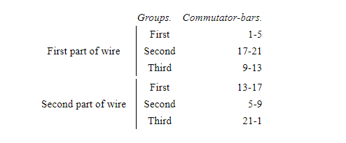
To further equalize the armature-coils at both sides of the plates that are in contact with the brushes, the winding and connecting up is effected in the following manner: The whole wire is wound upon the armature-core in two superimposed parts, which are thoroughly insulated from each other. Each of these two parts is composed of three separated groups of coils. The first group of coils of the first part of wire being wound and connected to the commutator-bars in the usual manner, this group is insulated and the second group wound; but the coils of this second group instead of being connected to the next following commutator-bars, are connected to the directly opposite bars of the commutator. The second group is then insulated and the third group wound, the coils of this group being connected to those bars to which they would be connected in the usual way. The wires are then thoroughly insulated and the second part of wire wound and connected in the same manner. Suppose, for instance, that there are twenty-four coils—that is, twelve in each part—and consequently twenty-four commutator-plates. There will be in each part three groups, each containing four coils, and the coils will be connected as follows:
| Groups. | Commutator Bars. | |
| First | 1—5 | |
| First part of wire | Second | 17—21 |
| Third | 9—13 | |
| First | 13—17 | |
| Second part of wire | Second | 5—9 |
| Third | 21—1 | |
In constructing the armature-core and winding and connecting the coils in the manner indicated, the passive or electrically-inactive wire is reduced to a minimum, and the coils at each side of the plates that are in contact with the brushes are practically equal, and in this way the electrical efficiency of the machine is increased.
The commutator-plates t are shown as outside the bearing b of the armature-shaft. The shaft H is tubular and split at the end portion and the wires are carried through the same in any usual manner and connected to the respective commutator-plates. The commutator-plates are upon a cylinder, u, and insulated, and this cylinder is to be properly placed and secured by expanding the split end of the shaft by a tapering screw-plug, v.
I do not claim herein the cores of the field-magnets converging towards the pole-pieces; nor do I claim the method of fastening the base to the lower field-magnet, as this has been claimed in my former application on dynamo-electric machines.
What I claim is—
1. In a dynamo-electric machine, the armature constructed of iron disks of various diameters arranged upon the shaft in such a manner that a series of iron bodies is formed, each diminishing in thickness from the center to the periphery, substantially as and for the purposes set forth.
2. In a dynamo-electric machine, the armature-core having iron disks of various diameters, in combination with inwardly-curved end disks, for the purposes and substantially as set forth.
3. In a dynamo-electric machine, an armature-core having inwardly-curved ends, in combination with the armature-coils, the crossing wires of which coils pass into the concave heads and project equally, substantially as set forth.
4. In a dynamo-electric machine, an armature having separate coils superimposed and connected to the commutator-plates in alternating groups, substantially as set forth.
5. An armature for dynamo-electric machines, having a core composed of disks of various diameters, in combination with separate superimposed coils connected to the commutator-plates in alternate groups, substantially as set forth.
6. In a dynamo-electric machine, the magnetic frame composed of the cores c c c c, the curved pole-pieces N S, and the connecting-frame with the curved and outwardly-projecting legs e e, substantially as described.
Signed by me this 12th day of January, 1886.
NIKOLA TESLA
Click images for higher-resolution
Source File: US Patent 359,748 - pdf
Chapter XL - The Martin Book
Nikola Tesla Direct Current Arc Lighting System
Thomas Commerford Martin
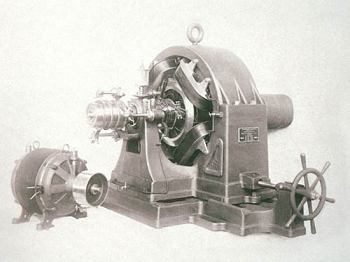
At one time, soon after his arrival in America, Mr. Tesla was greatly interested in the subject of arc lighting, which then occupied public attention and readily enlisted the support of capital. He therefore worked out a system which was confided to a company formed for its exploitation, and then proceeded to devote his energies to the perfection of the details of his more celebrated "rotary field" motor system. The Tesla arc lighting apparatus appeared at a time when a great many other lamps and machines were in the market, but it commanded notice by its ingenuity. Its chief purpose was to lessen the manufacturing cost and simplify the processes of operation.
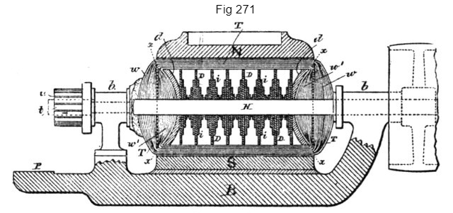
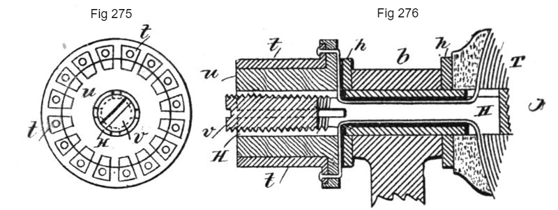
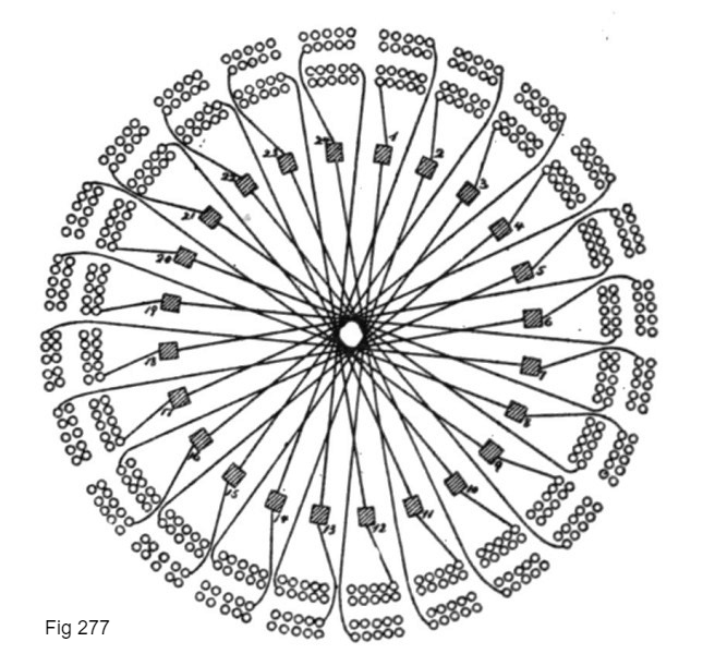
We will take up the dynamo first. Fig. 271 is a longitudinal section, and Fig. 272 a cross section of the machine. Fig. 273 is a top view, and Fig. 274 a side view of the magnetic frame. Fig. 275 is an end view of the commutator bars, and Fig. 276 is a section of the shaft and commutator bars. Fig. 277 is a diagram illustrating the coils of the armature and the connections to the commutator plates.
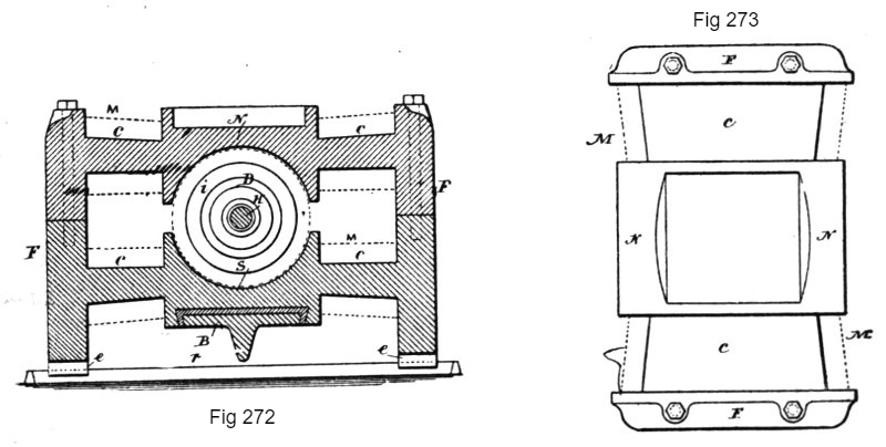
The cores c c c c of the field-magnets are tapering in both directions, as shown, for the purposes of concentrating the magnetism upon the middle of the pole-pieces.

The connecting-frame F F of the field-magnets is in the form indicated in the side view, Fig. 274, the lower part being provided with the spreading curved cast legs e e, so that the machine will rest firmly upon two base-bars, r r.
To the lower pole, S, of the field-magnet M is fastened, by means of babbitt or other fusible diamagnetic material, the base B, which is provided with bearings b for the armature-shaft H. The base B has a projection, P, which supports the brush-holders and the regulating devices, which are of a special character devised by Mr. Tesla.
The armature is constructed with the view to reduce to a minimum the loss of power due to Foucault currents and to the change of polarity, and also to shorten as much as possible the length of the inactive wire wound upon the armature core.
It is well known that when the armature is revolved between the poles of the field-magnets, currents are generated in the iron body of the armature which develop heat, and consequently cause a waste of power. Owing to the mutual action of the lines of force, the magnetic properties of iron, and the speed of the different portions of the armature core, these currents are generated principally on and near the surface of the armature core, diminishing in strength gradually toward the centre of the core. Their quantity is under some conditions proportional to the length of the iron body in the direction in which these currents are generated. By subdividing the iron core electrically in this direction, the generation of these currents can be reduced to a great extent. For instance, if the length of the armature-core is twelve inches, and by a suitable construction it is subdivided electrically, so that there are in the generating direction six inches of iron and six inches of intervening air-spaces or insulating material, the waste currents will be reduced to fifty per cent.
As shown in the diagrams, the armature is constructed of thin iron discs D D D, of various diameters, fastened upon the armature-shaft in a suitable manner and arranged according to their sizes, so that a series of iron bodies, i i i, is formed, each of which diminishes in thickness from the centre toward the periphery. At both ends of the armature the inwardly curved discs d d, of cast iron, are fastened to the armature shaft.
The armature core being constructed as shown, it will be easily seen that on those portions of the armature that are the most remote from the axis, and where the currents are principally developed, the length of iron in the generating direction is only a small fraction of the total length of the armature core, and besides this the iron body is subdivided in the generating direction, and therefore the Foucault currents are greatly reduced. Another cause of heating is the shifting of the poles of the armature core. In consequence of the subdivision of the iron in the armature and the increased surface for radiation, the risk of heating is lessened.
The iron discs D D D are insulated or coated with some insulating-paint, a very careful insulation being unnecessary, as an electrical contact between several discs can only occur at places where the generated currents are comparatively weak. An armature core constructed in the manner described may be revolved between the poles of the field magnets without showing the slightest increase of temperature.
The end discs, d d, which are of sufficient thickness and, for the sake of cheapness, of cast-iron, are curved inwardly, as indicated in the drawings. The extent of the curve is dependent on the amount of wire to be wound upon the armatures. In this machine the wire is wound upon the armature in two superimposed parts, and the curve of the end discs, d d, is so calculated that the first part—that is, practically half of the wire—just fills up the hollow space to the line x x; or, if the wire is wound in any other manner, the curve is such that when the whole of the wire is wound, the outside mass of wires, w, and the inside mass of wires, w', are equal at each side of the plane x x. In this case the passive or electrically-inactive wires are of the smallest length practicable. The arrangement has further the advantage that the total lengths of the crossing wires at the two sides of the plane x x are practically equal.
To equalize further the armature coils at both sides of the plates that are in contact with the brushes, the winding and connecting up is effected in the following manner: The whole wire is wound upon the armature-core in two superimposed parts, which are thoroughly insulated from each other. Each of these two parts is composed of three separated groups of coils. The first group of coils of the first part of wire being wound and connected to the commutator-bars in the usual manner, this group is insulated and the second group wound; but the coils of this second group, instead of being connected to the next following commutator bars, are connected to the directly opposite bars of the commutator. The second group is then insulated and the third group wound, the coils of this group being connected to those bars to which they would be connected in the usual way. The wires are then thoroughly insulated and the second part of wire is wound and connected in the same manner.
Suppose, for instance, that there are twenty-four coils—that is, twelve in each part—and consequently twenty-four commutator plates. There will be in each part three groups, each containing four coils, and the coils will be connected as follows:
| Groups. | Commutator Bars. | |
| First | 1—5 | |
| First part of wire | Second | 17—21 |
| Third | 9—13 | |
| First | 13—17 | |
| Second part of wire | Second | 5—9 |
| Third | 21—1 | |
In constructing the armature core and winding and connecting the coils in the manner indicated, the passive or electrically inactive wire is reduced to a minimum, and the coils at each side of the plates that are in contact with the brushes are practically equal. In this way the electrical efficiency of the machine is increased.
The commutator plates t are shown as outside the bearing b of the armature shaft. The shaft H is tubular and split at the end portion, and the wires are carried through the same in the usual manner and connected to the respective commutator plates. The commutator plates are upon a cylinder, u, and insulated, and this cylinder is properly placed and then secured by expanding the split end of the shaft by a tapering screw plug, v.
The arc lamps invented by Mr. Tesla for use on the circuits from the above described dynamo are those in which the separation and feed of the carbon electrodes or their equivalents is accomplished by means of electro-magnets or solenoids in connection with suitable clutch mechanism, and were designed for the purpose of remedying certain faults common to arc lamps.
Previous Chapter --- Contents --- Next Chapter
Related Patents
390,414
Dynamo-Electric Machine - April 23, 1888
335,786
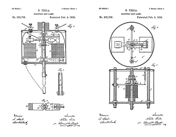
Electric-Arc Lamp - March 30, 1885
Tesla's Arc-Light Technology
Automatic Lamps, Commutators, Regulators, DC Generator or "Dynamo"
To the Archive Page Discussion on Tesla's Technology

Lab-Tesla disclosures on the technology just presented
A NEW SYSTEM OF ALTERNATE CURRENT MOTORS AND TRANSFORMERS
Paper by Nikola Tesla read to the American Institute of Electrical Engineers on May 16, 1888
Tesla's Laboratory Power