390,414
DYNAMO-ELECTRIC MACHINE - April 23, 1888
UNITED STATES PATENT OFFICE
NIKOLA TESLA, OF NEW YORK, N. Y., ASSIGNOR TO THE TESLA ELECTRIC COMPANY, OF SAME PLACE
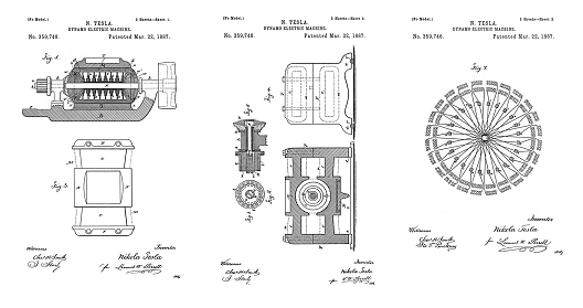
Nikola Tesla Patent 390,414 DYNAMO-ELECTRIC MACHINE
SPECIFICATION forming part of Letters Patent No. 390,414 dated October 2, 1888.
Application filed April 23, 1888. Serial No. 271,626. (No model.)
To all whom it may concern:
Be it known that I, NIKOLA TESLA, a subject of the Emperor of Austria, from Smiljan, Lika, border country of Austria-Hungary, now residing at New York, in the county and State of New York, have invented certain new and useful Improvements in Dynamo-Electric Machines, of which the following is a specification, reference being had to the drawings accompanying and forming a part of the same.
In certain patents granted to Charles F. Peck and myself—notably in Patents No. 381,968 and No. 382,280, May 1, 1888 — I have shown and described a plan of constructing and operating motors, transformers, and the like, by alternating currents conveyed through two or more independent circuits from a generator having such relation to the motors or transformers as to produce therein a progressive movement of the magnetic poles or lines of force. In the said applications the descriptions and illustrations of the generators were confined to those types of alternating current machine in which the current generating coils are independent or separate; but I have found that the ordinary forms of continuous current dynamos now in use may be readily and cheaply adapted to my system, or utilized both as continuous and alternating current generators with but slight changes in their construction. The mode of effecting this forms the substance of my present application.
Generally stated, the plan pursued by me in carrying out this invention is as follows: On the shaft of a given generator, either in place of or in addition to the regular commutator, I secure as many pairs of insulated collecting-rings as there are circuits to be formed. Now, it will be understood that in the operation of any dynamo-electric generator the currents in the coils in their movement through the field of force undergo different phases—that is to say, at different positions of the coils the currents have certain directions and certain strengths—and that in my improved motors or transformers it is necessary that the currents in the energizing-coils should undergo a certain order of variations in strength and direction. Hence, the further step—viz., the connection between the induced or generating coils of the machine and the contact-rings from which the currents are to be taken off—will be determined solely by what order of variations of strength and direction in the currents is desired for producing a given result in the electrical translating device. This may be accomplished in various ways; but in the drawings I have given typical instances only of the best and most practicable ways of applying the invention to three of the best-known types of machines, in order to illustrate the principle and to enable anyone skilled in the art to apply the invention in any other case or under any modified conditions which the circumstances of particular cases may require.
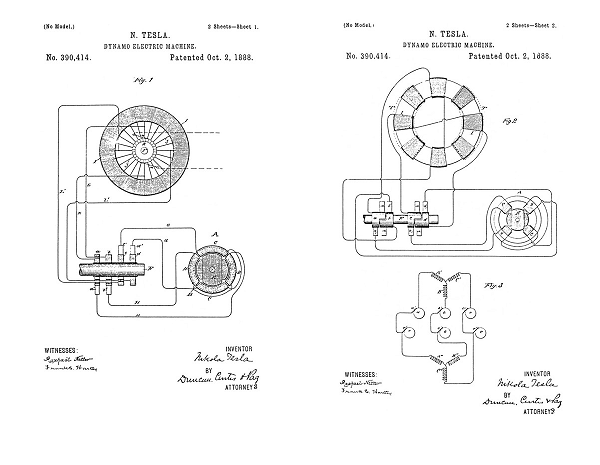
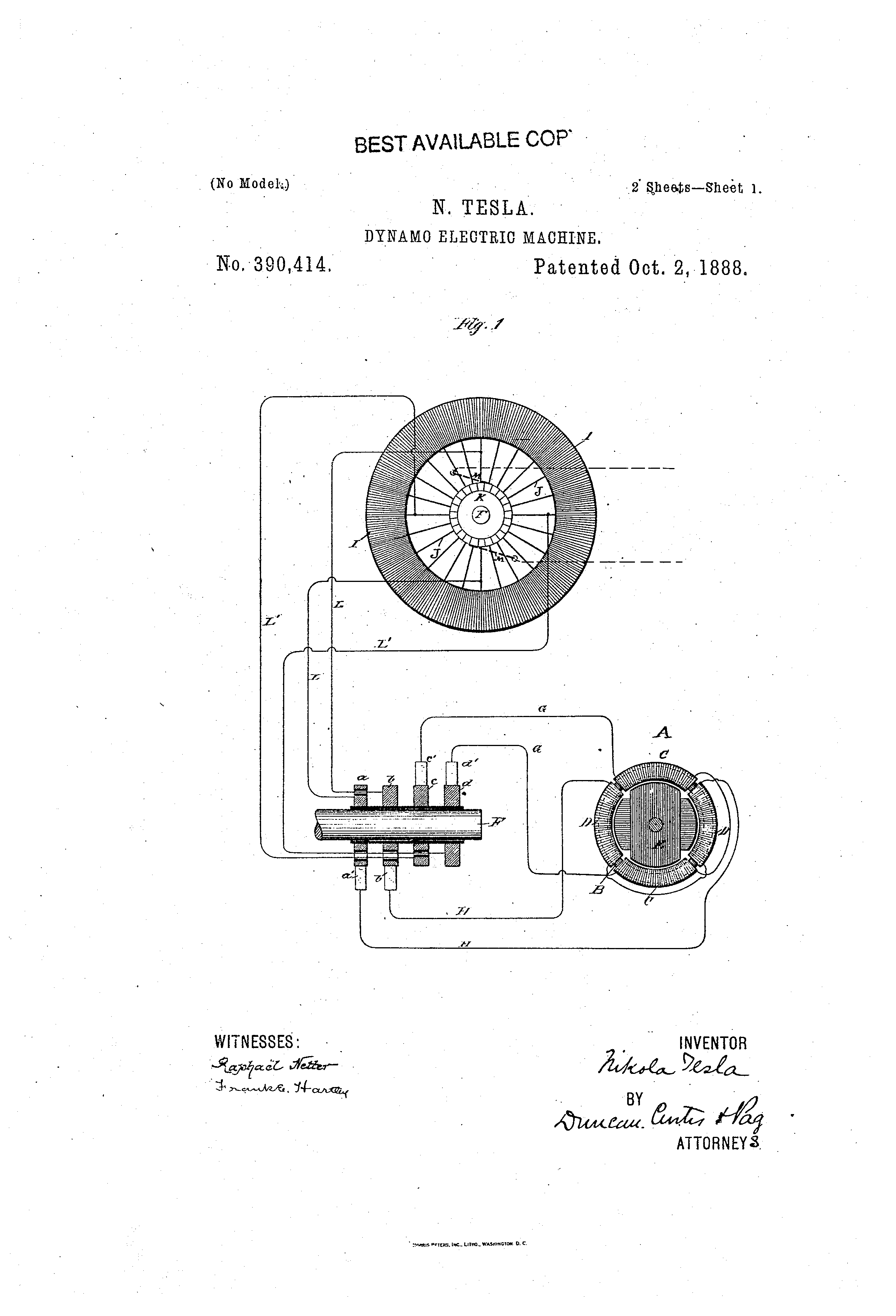
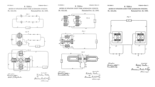
Figure 1 is a diagram illustrative of the mode of applying the invention to the well-known type of closed or continuous circuit machines. Fig. 2 is a similar diagram containing an armature with separate coils connected diametrically, or what is generally called an “open-circuit” machine. Fig. 3 is a diagram showing the application of the invention to a machine the armature-coils of which have a common joint.
Referring to Fig. 1, let A represent one of my improved motors or transformers, which, for convenience, I shall designate a “converter,” which consists of an annular core, B, wound with four independent coils, C and D, those diametrically opposite being connected together so as to co-operate in pairs in establishing free poles in the ring, the tendency of each pair being to fix the poles at ninety degrees from the other. There may be an armature, E, within the ring, which is wound with coils closed upon themselves. The object is to pass through coils C D currents of such relative strength and direction as to produce a progressive shifting or movement of the points of maximum magnetic effect around the ring, and to thereby maintain a rotary movement of the armature. I therefore secure to the shaft F of the generator four insulated contact-rings, a b c d, upon which I cause to bear the collecting-brushes a' b' c' d', connected by wires G G H H, respectively, with the terminal of coils C and D.
Assume, for the sake of illustration, that the coils D D are to receive the maximum and coils C C at the same instant the minimum current, so that the polar line may be midway between the coils D D, the rings a b would therefore be connected to the continuous armature-coil at its neutral points with respect to the field or the point corresponding with that of the ordinary commutator-brushes, and between which exists the greatest difference of potential, while rings c d would be connected to two points in the coil, between which exists no difference of potential. The best results will be obtained by making these connections at points equidistant from one another, as shown. These connections are easiest made by using wires L between the rings and the loops or wires J, connecting the coil I to the segments of the commutator K. When the converters are made in this manner, it is evident that the phases of the currents in the sections of the generator-coil will be reproduced in the converter coils. For example, after turning through an arc of ninety degrees the conductors L L, which before conveyed the maximum current, will receive the minimum current by reason of the change in the position of their coils, and it is evident that for the same reason the current in said coils has gradually fallen from the maximum to the minimum in passing through the arc of ninety degrees. In this special plan of connections the rotation of the magnetic poles of the converter will be synchronous with that of the armature-coils of the generator; and the result will be the same, whether the energizing-circuits are derivations from a continuous armature-coil or from independent coils, as in my previous devices.
I have shown in Fig. 1, in dotted lines, the brushes M M in their proper normal position. In practice these brushes may be removed from the commutator and the field of the generator excited by an external source of current; or the brushes may be allowed to remain on the commutator and to take off a converted current to excite the field, or to be used for other purposes.
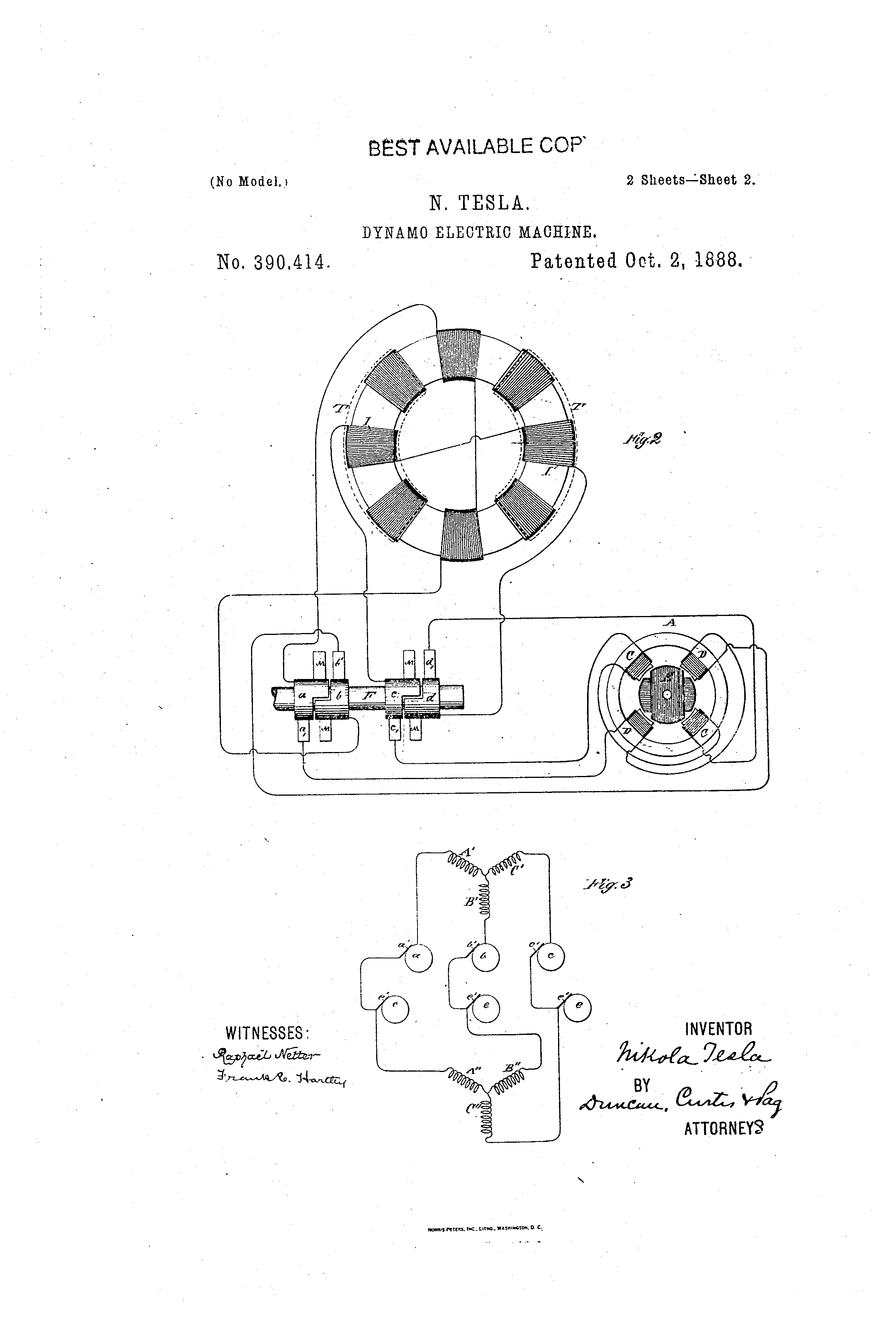
In a certain well-known class of machines the armature contains a number of coils the terminals of which connect to commutator segments, the coils being connected across the armature in pairs. This type of machine is represented in Fig. 2. In this machine each pair of coils goes through the same phases as the coils in some of the generators I have shown, and it is obviously only necessary to utilize them in pairs or sets to operate one of my converters by extending the segments of the commutators belonging to each pair of coils and causing a collecting-brush to bear on the continuous portion of each segment. In this way two or more circuits may be taken off from the generator, each including one or more pairs of sets of coils, as may be desired.
In Fig. 2 I I represent the armature-coils, T T the poles of the field-magnet, and F the shaft carrying the commutators, which are extended to form continuous portions a b c d. The brushes bearing on the continuous portions for taking off the alternating currents are represented by a' b' c' d'. The collecting-brushes, or those which may be used to take off the direct current, are designated by M M. Two pairs of the armature-coils and their commutators are shown in the figure as being utilized; but all may be utilized in a similar manner.
There is another well-known type of machine in which three or more coils, A' B' C', on the armature have a common joint, the free ends being connected to the segments of a commutator. This form of generator is illustrated in Fig. 3. In this case each terminal of the generator is connected directly or in derivation to a continuous ring, a b c, and collecting-brushes a' b' c', bearing thereon, take off the alternating currents that operate the motor. It is preferable in this case to employ a motor or transformer with three energizing-coils, A'' B'' C'', placed symmetrically with those of the generator, and the circuits from the latter are connected to the terminals of such coils either directly—as when they are stationary—or by means of brushes e' and contact-rings e. In this, as in the other cases, the ordinary commutator may be used on the generator, and the current taken from it utilized for exciting the generator field-magnets or for other purposes.
These examples serve to illustrate the principle of the invention. It will be observed that in any case it is necessary only to add the continuous contact or collecting rings and to establish the connections between them and the appropriate coils.
It will be understood that this invention is applicable to other types of machine—as, for example, those by which the induced coils are stationary and the brushes and magnet revolve; but the manner of its application is obvious to one skilled in the art.
Having now described my invention, what I claim is—
1. The combination, with a converter having independent energizing-coils, of a continuous or direct current dynamo or magneto machine, and intermediate-circuits permanently connected as suitable points to the induced or generating coils of the generator, as herein set forth.
2. The combination, with a converter provided with independent energizing-circuits, of a continuous or direct current generator provided with continuous collecting-rings connected in derivation to the armature-coils to form the terminal of circuits corresponding to those of the converter, as herein set forth.
NIKOLA TESLA
Click images for higher-resolution
Source File: US Patent 390,414 - pdf
Chapter V - The Martin Book
Utilizing Familiar Types of Generator of the Continuous Current Type
The preceding descriptions have assumed the use of alternating current generators in which, in order to produce the progressive movement of the magnetic poles, or of the resultant attraction of independent field magnets, the current generating coils are independent or separate. The ordinary forms of continuous current dynamos may, however, be employed for the same work, in accordance with a method of adaptation devised by Mr. Tesla. As will be seen, the modification involves but slight changes in their construction, and presents other elements of economy.
On the shaft of a given generator, either in place of or in addition to the regular commutator, are secured as many pairs of insulated collecting-rings as there are circuits to be operated. Now, it will be understood that in the operation of any dynamo electric generator the currents in the coils in their movement through the field of force undergo different phases—that is to say, at different positions of the coils the currents have certain directions and certain strengths—and that in the Tesla motors or transformers it is necessary that the currents in the energizing coils should undergo a certain order of variations in strength and direction. Hence, the further step—viz., the connection between the induced or generating coils of the machine and the contact-rings from which the currents are to be taken off—will be determined solely by what order of variations of strength and direction in the currents is desired for producing a given result in the electrical translating device. This may be accomplished in various ways; but in the drawings we give typical instances only of the best and most practicable ways of applying the invention to three of the leading types of machines in widespread use, in order to illustrate the principle.
Fig. 25 is a diagram illustrative of the mode of applying the invention to the well-known type of "closed" or continuous circuit machines. Fig. 26 is a similar diagram embodying an armature with separate coils connected diametrically, or what is generally called an "open-circuit" machine. Fig. 27 is a diagram showing the application of the invention to a machine the armature-coils of which have a common joint.
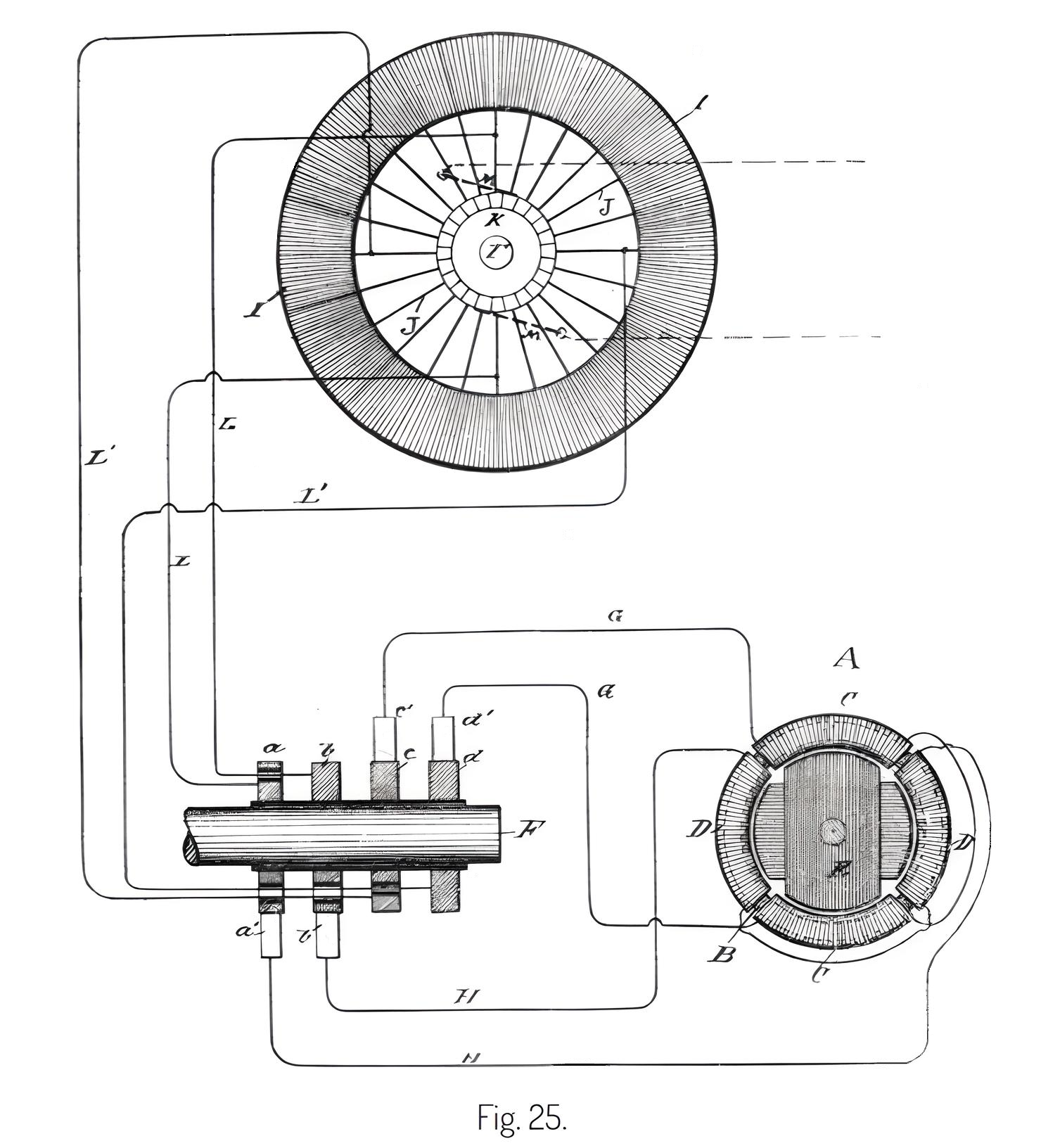
Referring to Fig. 25, let A represent a Tesla motor or transformer which, for convenience, we will designate as a "converter." It consists of an annular core, wound with four independent coils, C and those diametrically opposite being connected together so as to co-operate in pairs in establishing free poles in the ring, the tendency of each pair being to fix the poles at ninety degrees from the other. There may be an armature, within the ring, which is wound with coils closed upon themselves. The object is to pass through coils C D currents of such relative strength and direction as to produce a progressive shifting or movement of the points of maximum magnetic effect around the ring, and to thereby maintain a rotary movement of the armature. There are therefore secured to the shaft F of the generator, four insulated contact-rings, a b c upon which bear the collecting-brushes a' b' c' connected by wires G G H respectively, with the terminals of coils C and
Assume, for sake of illustration, that the coils D D are to receive the maximum and coils C C at the same instant the minimum current, so that the polar line may be midway between the coils D The rings a b would therefore be connected to the continuous armature-coil at its neutral points with respect to the field, or the point corresponding with that of the ordinary commutator brushes, and between which exists the greatest difference of potential; while rings c d would be connected to two points in the coil, between which exists no difference of potential. The best results will be obtained by making these connections at points equidistant from one another, as shown. These connections are easiest made by using wires L between the rings and the loops or wires connecting the coil I to the segments of the commutator When the converters are made in this manner, it is evident that the phases of the currents in the sections of the generator coil will be reproduced in the converter coils. For example, after turning through an arc of ninety degrees the conductors L which before conveyed the maximum current, will receive the minimum current by reason of the change in the position of their coils, and it is evident that for the same reason the current in these coils has gradually fallen from the maximum to the minimum in passing through the arc of ninety degrees. In this special plan of connections, the rotation of the magnetic poles of the converter will be synchronous with that of the armature coils of the generator, and the result will be the same, whether the energizing circuits are derivations from a continuous armature coil or from independent coils, as in Mr. Tesla's other devices.
In Fig. 25, the brushes M M are shown in dotted lines in their proper normal position. In practice these brushes may be removed from the commutator and the field of the generator excited by an external source of current; or the brushes may be allowed to remain on the commutator and to take off a converted current to excite the field, or to be used for other purposes.
In a certain well-known class of machines known as the "open circuit," the armature contains a number of coils the terminals of which connect to commutator segments, the coils being connected across the armature in pairs. This type of machine is represented in Fig. 26. In this machine each pair of coils goes through the same phases as the coils in some of the generators already shown, and it is obviously only necessary to utilize them in pairs or sets to operate a Tesla converter by extending the segments of the commutators belonging to each pair of coils and causing a collecting brush to bear on the continuous portion of each segment. In this way two or more circuits may be taken off from the generator, each including one or more pairs or sets of coils as may be desired.
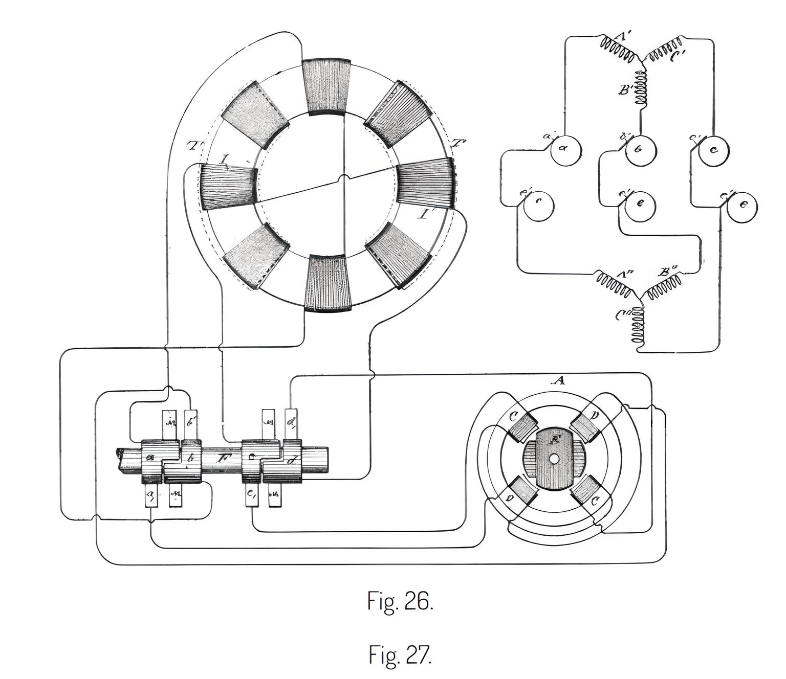
In Fig. 26 I I represent the armature coils, T T the poles of the field magnet, and F the shaft carrying the commutators, which are extended to form continuous portions a b c The brushes bearing on the continuous portions for taking off the alternating currents are represented by a' b' c' The collecting brushes, or those which may be used to take off the direct current, are designated by M Two pairs of the armature coils and their commutators are shown in the figure as being utilized; but all may be utilized in a similar manner.
There is another well-known type of machine in which three or more coils, A' B' on the armature have a common joint, the free ends being connected to the segments of a commutator. This form of generator is illustrated in Fig. 27. In this case each terminal of the generator is connected directly or in derivation to a continuous ring, a b and collecting brushes, a' b' bearing thereon, take off the alternating currents that operate the motor. It is preferable in this case to employ a motor or transformer with three energizing coils, A'' B'' placed symmetrically with those of the generator, and the circuits from the latter are connected to the terminals of such coils either directly—as when they are stationary—or by means of brushes e' and contact rings In this, as in the other cases, the ordinary commutator may be used on the generator, and the current taken from it utilized for exciting the generator field-magnets or for other purposes.
Previous Chapter --- Contents --- Next Chapter
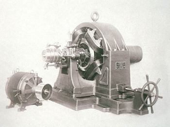
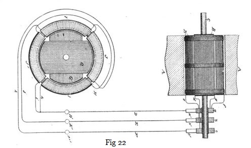
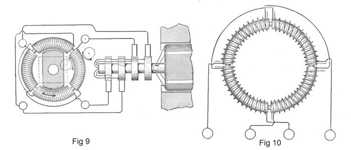
Note: This adaptation was used on Tesla's Dynamo Electric Machine - 359,748 while Tesla was still based in Rahway NJ. The machine was routinely connected in both 2-phase and 3-phase configurations, and up to 6-phases were experimented with. The alternating current was used to develop and test the motors shown in Fig 298 and Fig 299 in Tesla's World's Fair Exhibit: these "motors" were also applied as alternating current generators, and there were a variety of different armature designs prepared and tested with this equipment. This same generator, 359,748, with the modifications shown in patent above, maintained the DC output from the commutator. The resulting machine is illustrated in the diagram shown in Fig 165 in the Martin Book. This machine was eventually equipped with synchronous circuit controllers and synchronous rotary spark gaps such as shown in US Patent 568,180. It was used to power synchronous oscillators with at least 3-phases.
Polyphase
Modifications and Expansions of the Tesla Polyphase Systems
Self-Exciting Dynamos and Alternators
Rectification, Energy Conversion
Tesla's Arc-Light Technology
Automatic Lamps, Commutators, Regulators, DC Generator or "Dynamo"
To the Archive Page Discussion on Tesla's Technology
Lab-Tesla disclosures on the technology just presented
A NEW SYSTEM OF ALTERNATE CURRENT MOTORS AND TRANSFORMERS
Paper by Nikola Tesla read to the American Institute of Electrical Engineers on May 16, 1888
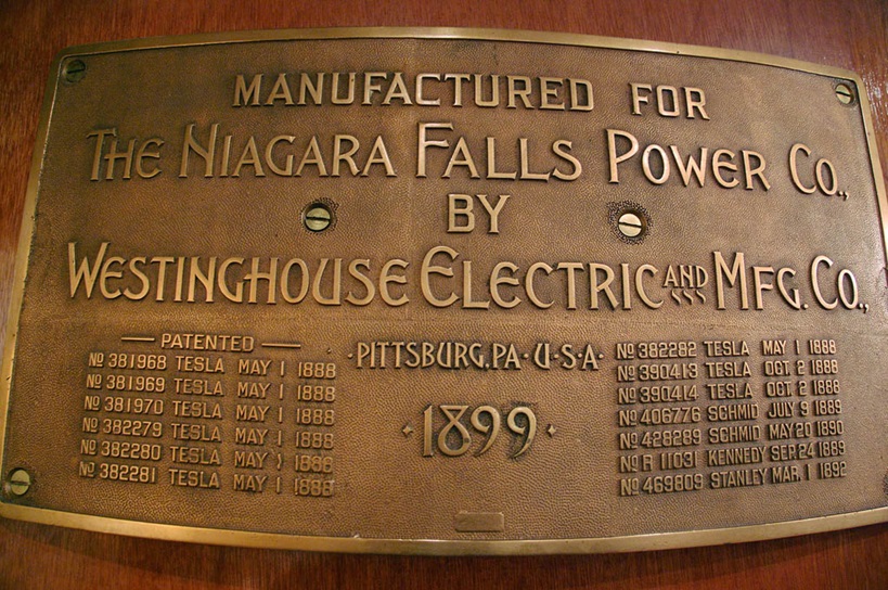
381968 - 381969 - 381970 - 382279 - 382280 - 382281 - 382282 - 390413 - 390414
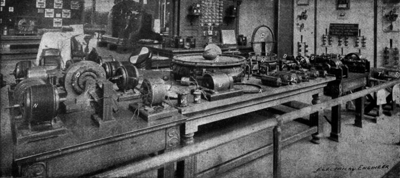
Mr. Tesla's Personal Exhibit at the World's Fair
Chapter XLII - The Martin Book
Tesla's Laboratory Power