Mr. Tesla's Personal Exhibit at the World's Fair
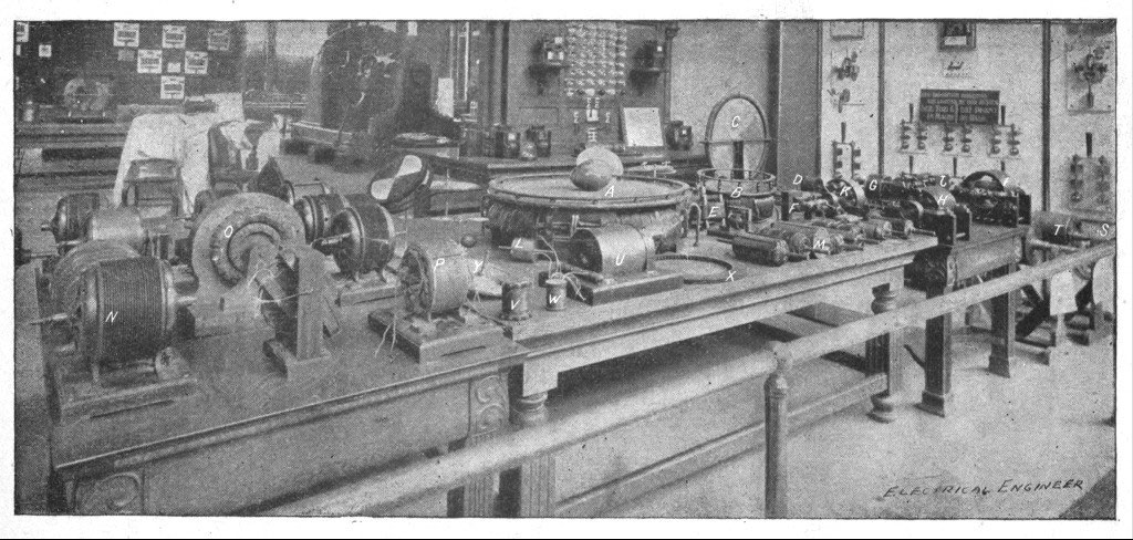
Fig. 297, labeled - Click for higher resolution
Chicago World's Fair - Columbian Exposition - 1893
Chapter XLII - The Martin Book
First published as an article in The Electrical Engineer - November 29th, 1893
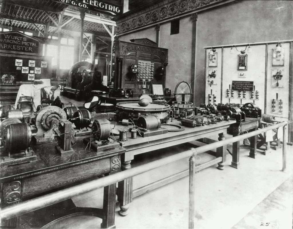
Fig 297 - Full - No Edits - Detre Library & Archives, Heinz History Center. Hosted by: University of Pittsburgh Library System
Thomas Commerford Martin
While the exhibits of firms engaged in the manufacture of electrical apparatus of every description at the Chicago World's Fair, afforded the visitor ample opportunity for gaining an excellent knowledge of the state of the art, there were also numbers of exhibits which brought out in strong relief the work of the individual inventor, which lies at the foundation of much, if not all, industrial or mechanical achievement. Prominent among such personal exhibits was that of Mr. Tesla, whose apparatus occupied part of the space of the Westinghouse Company, in the Electricity Building.
This apparatus represented the results of work and thought covering a period of ten years. It embraced a large number of different alternating motors and Mr. Tesla's earlier high frequency apparatus. The motor exhibit consisted of a variety of fields and armatures for two, three and multiphase circuits, and gave a fair idea of the gradual evolution of the fundamental idea of the rotating magnetic field. The high frequency exhibit included Mr. Tesla's earlier machines and disruptive discharge coils and high frequency transformers, which he used in his investigations and some of which are referred to in his papers printed in this volume.
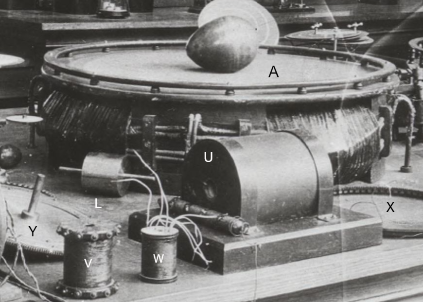
Tesla's "Egg of Columbus" - A
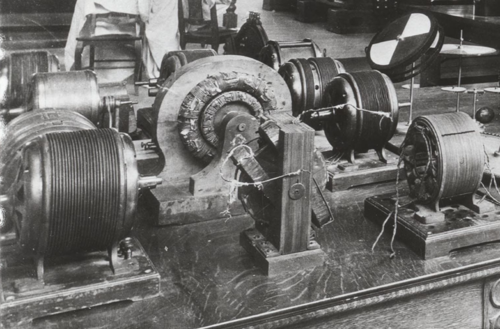
Fig 297 shows a view of part of the exhibits containing the motor apparatus. Among these is shown at A a large ring intended to exhibit the phenomena of the rotating magnetic field. The field produced was very powerful and exhibited striking effects, revolving copper balls and eggs and bodies of various shapes at considerable distances and at great speeds. This ring was wound for two-phase circuits, and the winding was so distributed that a practically uniform field was obtained. This ring was prepared by Mr. C. F. Scott, electrician of the Westinghouse Electric and Manufacturing Company. *
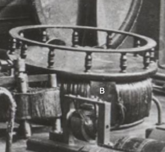
A smaller ring, shown at B (Fig 297), was arranged like the one exhibited at A but designed especially to exhibit the rotation of an armature in a rotating field. In connection with these two rings there was an interesting exhibit shown by Mr. Tesla which consisted of a magnet with a coil, the magnet being arranged to rotate in bearings. With this magnet he first demonstrated the identity between a rotating field and a rotating magnet; the latter, when rotated, exhibited the same phenomena as the rings when they were energized by currents of differing phase. Another prominent exhibit was a model illustrated at C which was a two-phase motor, as well as an induction motor and transformer. It consists of a large outer ring of laminated iron wound with two superimposed, separated windings which can be connected in a variety of ways. This is one of the first models used by Mr. Tesla as an induction motor and rotating transformer. The armature was either a steel or wrought iron disc with a closed coil. When the motor was operated from a two-phase generator the windings were connected in two groups, as usual. When used as an induction motor, the current induced in one of the windings of the ring was passed through the other winding of the ring and so the motor operated with only two wires. When used as a transformer the outer winding served, for instance, as the secondary and the inner as the primary. The model shown at - D is one of the earliest rotating field motors, consisting of a thin iron ring wound with two sets of coils and an armature consisting of a series of steel discs partly cut away and arranged on a small arbor.
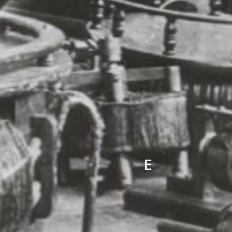
At E is shown one of the first rotating field or induction motors used for the regulation of an arc-lamp and for other purposes. It comprises a ring of discs with two sets of coils having different self-inductions, one set being of German silver and the other of copper wire. The armature is wound with two closed-circuited coils at right angles to each other. To the armature shaft are fastened levers and other devices to effect the regulation.
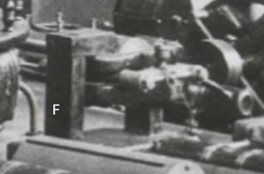
At F is shown a model of a magnetic lag motor; this embodies a casting with pole projections protruding from two coils between which is arranged to rotate a smooth iron body. When an alternating current is sent through the two coils the pole projections of the field and armature are similarly magnetized, and upon the cessation or reversal of the current the armature and field repel each other and rotation is produced this way.
Another interesting exhibit, shown at G , is an early model of a two field motor energized by currents of different phase. There are two independent fields of laminated iron joined by brass bolts; in each field is mounted an armature, both armatures being on the same shaft. The armatures were originally so arranged as to be placed in any position relatively to each other, and the fields also were arranged to be connected in a number of ways. The motor has served for the exhibition of a number of features; among other things it has been used as a dynamo for the production of currents of any frequency between wide limits. In this case the field, instead of being energized by direct current, was energized by currents differing in phase, which produced a rotation of the field; the armature was then rotated in the same or in opposite direction to the movement of the field; and so any number of alternations of the currents induced in the armature, from a small to a high number, determined by the frequency of the energizing coils and speed of the armature was obtained.
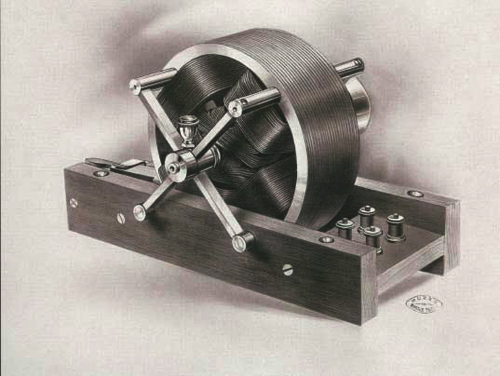
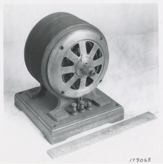
Fig 298
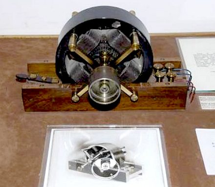
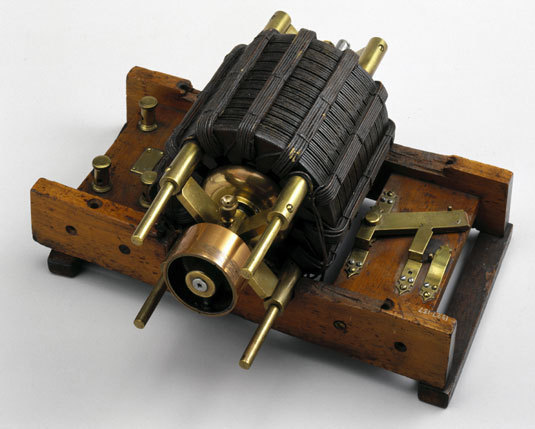
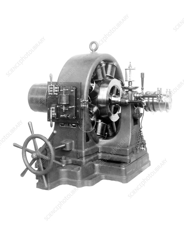
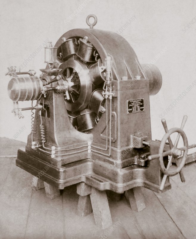
Fig 298a - See US Patent 390,721 - This motor/generator (it was used for both) is photographed above and below with the armature type shown in Fig 305 below, and later applied in the Niagara Falls generators.
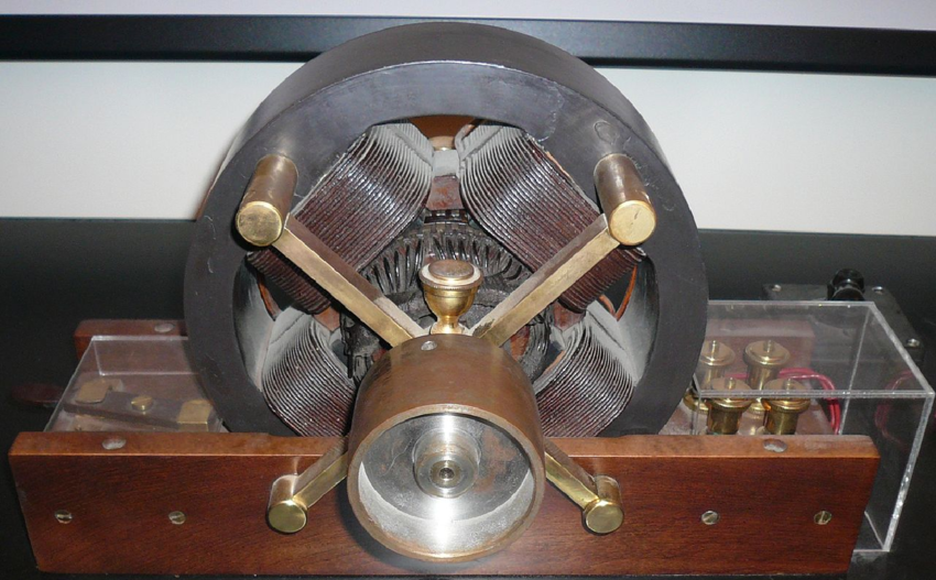
Closeup of the motor shown in Fig 298, mounted with the armature described in Fig 305 below. This basic armature design was used in rotational armatures as shown, up to 500 hp, and was used in the stationary armatures of the Niagara Falls generators.
The models H I J represent a variety of rotating field, synchronous motors which are of special value in long distance transmission work. The principal embodied in these motors was enunciated by Mr. Tesla in his lecture before the American Institute of Electrical Engineers, in May, 1888. It involves the production of the rotating field in one of the elements of the motor by currents differing in phase and energizing the other element by direct currents. The armatures are of the two and three phase type.
K is a model of a motor shown in an enlarged view in Fig 298. This machine, together with that shown in Fig 299, was exhibited at the same lecture, in May, 1888. They were the first rotating field motors which were independently tested, having for that purpose been placed in the hands of Prof. Anthony in the winter of 1887-88. From these tests it was shown that the efficiency and output of these motors was quite satisfactory in every respect..
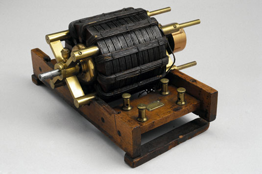
Fig 299
One of the original AC Tesla Induction Motors photographed at the British Science Museum in London. This motor was referenced in T.C. Martin's book as loaned by Tesla to Prof. Ayrton in England. When Tesla traveled to London for his lecture in 1892 the motor was gifted. Additional images and text in the link: https://www.teslasociety.com/hall_of_fame.htm
Both this motor and the motor shown in Fig 298 were used as alternating current generators: brass frame extensions as shown above and below were mounted to hold the brushes. Armatures with pickup rings were used as shown in
U.S. Patent 390,721, and in Figs 309 and 310 below.
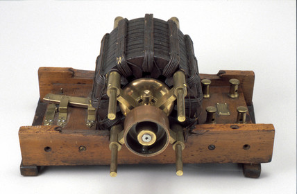
It was intended to exhibit the model shown in Fig 299, but it was unavailable for that purpose owing to the fact that it was some time ago handed over to the care of Prof. Ayrton in England. This model was originally provided with twelve independent coils; this number, as Mr. Tesla pointed out in his first lecture, being divisible by two and three, was selected in order to make various connections for two and three-phase operations, and during Mr. Tesla's experiments was used in many ways with from two to six phases. The model, Fig 298, consists of a magnetic frame of laminated iron with four polar projections between which an armature is supported on brass bolts passing through the frame. A great variety of armatures was used in connection with these two and other fields. Some of the armatures are shown in front on the table, Fig 297, and several are shown enlarged in Figs 300-310. An interesting exhibit is that shown at L, Fig 297. This is an armature of hardened steel which was used in a demonstration before the Society of Arts in Boston, by Prof. Anthony. Another curious exhibit is shown enlarged in Fig 301. This consists of thick discs of wrought iron placed lengthwise, with a mass of copper cast around them. The discs were arranged longitudinally to afford an easier starting by reason of the induced current formed in the iron discs, which differed in phase from those in the copper. This armature would start with a single circuit and run in synchronism, and represents one of the earliest types of such an armature.
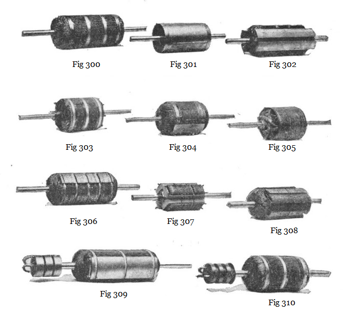
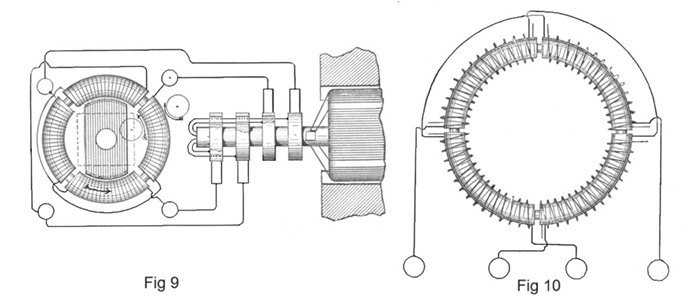
Fig 305 is another striking exhibit. This is one of the earliest types of an armature with holes beneath the periphery, in which copper conductors are imbedded. The armature has eight closed circuits and was used in many different ways. Fig 304 is a type of synchronous armature consisting of a block of soft steel wound with a coil closed upon itself. This armature was used in connection with the field shown in Fig 298 and gave excellent results.
Fig 302 represents a synchronous armature with a large coil around a body of iron. There is another very small coil at angles to the first. This small coil was used for the purpose of increasing the starting torque and was found very effective in this connection. Figs 306 and 308 show a favorite construction of armature; the iron body is made up of two sets of discs cut away and placed at right angles to each other, the interstices being wound with coils. The one shown in Fig 308 is provided with an additional groove on each of the projections formed by the discs, for the purpose of increasing the starting torque by a wire wound in these projections. Fig 307 is a form of armature similarly constructed, but with four independent coils wound upon the four projections. This armature was used to reduce the speed of the motor in reference to that of the generator. Fig 300 is still another armature with a great number of independent circuits closed upon themselves, so that all the dead points on the armature are done away with, and the armature has a large starting torque. Fig 303 is another type of armature for a four-pole motor but with coils wound upon a smooth surface. A number of these armatures have hollow shafts, as they have been used in many ways. Figs 309 and 310 represent armatures to which either alternating or direct current was conveyed by means of sliding rings. Fig 309 consists of a soft iron body with a single coil wound around it, the ends of the coil being connected to two sliding rings to which, usually, direct current was conveyed. The armature shown in Fig 310 has three insulated rings on a shaft and was used in connection with two or three phase circuits.
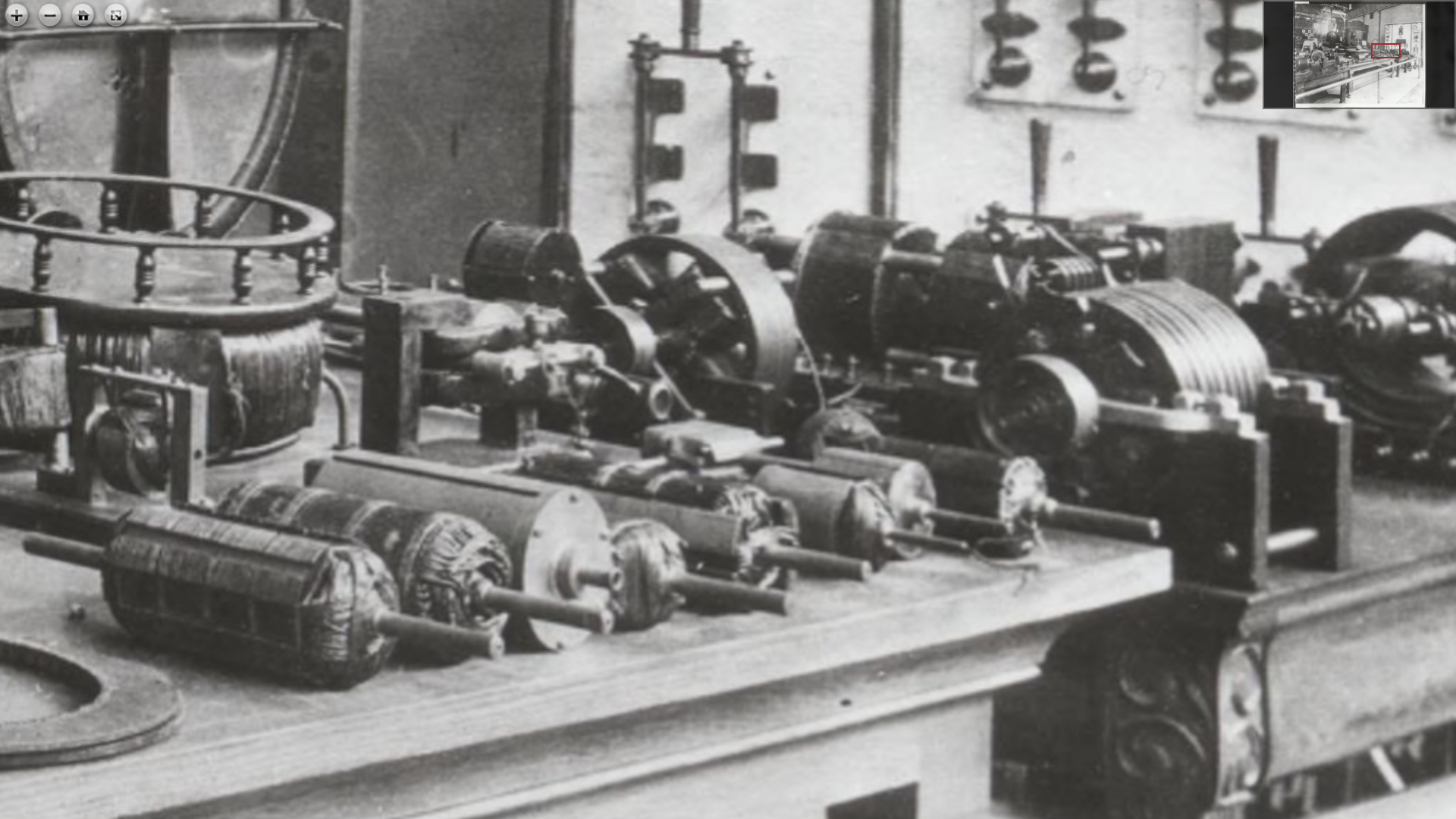
All these models shown represent early work, and the enlarged engravings are made from photographs taken early in 1888. There is a great number of other models which were exhibited, but which were not brought out sharply in the engraving, Fig 297. For example at M is a model of a motor comprising an armature with a hollow shaft wound with two or three coils for two or three-phase circuits; the armature was arranged to be stationary and circuits were connected directly to the generator. Around the armature was arranged to rotate on its shaft a casting forming six closed circuits. On the outside of this casting was turned smooth and the belt was placed on it for driving any desired appliance. This also is a very early model.
On the left side of the table there are seen a large variety of models, N, O, P etc., with fields of various shapes. Each of these models involves some distinct idea and they all represent gradual development chiefly interesting as showing Mr. Tesla's efforts to adapt his system to the existing high frequencies.
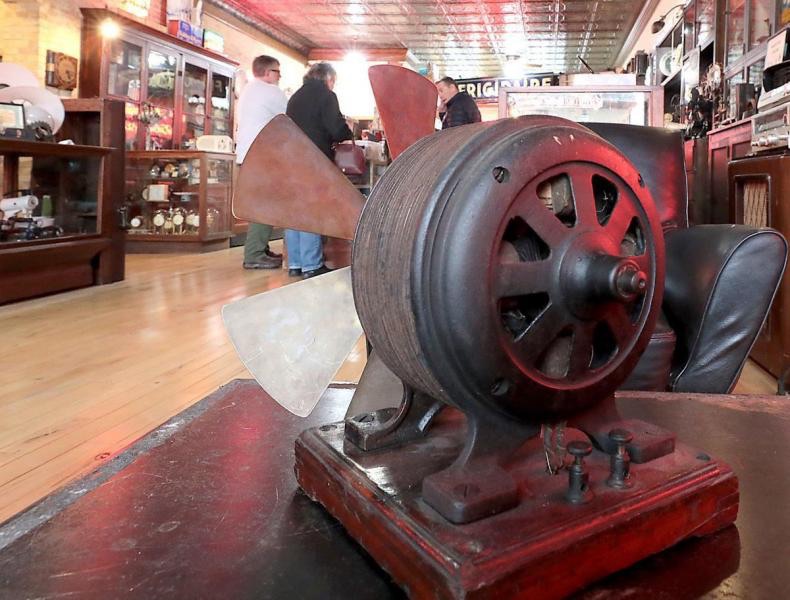
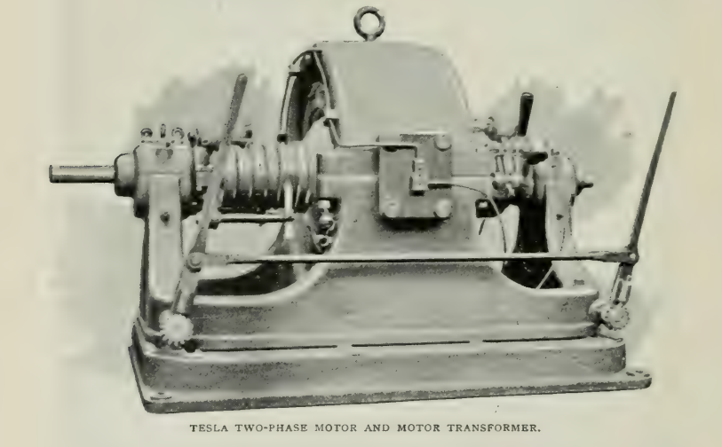
N
[- Insert Note: N - Tesla 1/4 horsepower load-rated synchronous 2-phase motor constructed in Tesla's laboratory and photographed there in early 1888. This motor was displayed at Tesla's Personal Exhibit at the World's Fair. Nearly identical clones of this motor were manufactured by Westinghouse in several sizes. Larger clones of this motor were used in the Electricity Building for demonstrations (photo below) - Tesla used this motor above, N, and nearly identical clones of this motor that were manufactured by Westinghouse, in his laboratory for wireless work. The motors were powered by the isochronous generator Tesla demonstrated at the Fair. The frequency locked motors turned: high-frequency alternators, - rotary spark gaps - and - circuit controllers. - They were also used to drive clockwork to rotate coherers and rotational receivers. The synchronous motors below, H, I, J, as well as the motor shown in Fig 298 and a larger motor of the type shown in Fig 299, were also used to rotate small devices in early wireless research, frequently powered by the same generator. By mid-1889, Tesla could obtain 2-phase synchronous motors, and alternators, off-the-shelf from Westinghouse. -]
Image preserved by the Detre Library & Archives, Heinz History Center - Hosted by: University of Pittsburgh Library System

Westinghouse Electric and Manufacturing Co. clone of the Tesla motor N. These motors were routinely used in frequency stable wireless work. This was the first Tesla motor marketed and it was sold as a fan.
On the right side of the table, at S, T, are shown, on separate supports, larger and more perfected armatures of commercial motors, and in the space around the table a variety of motors and generators supplying currents to them was exhibited.
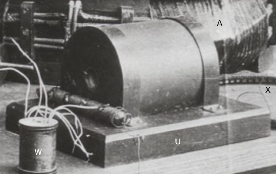
W - Appears to be a small harmonic transformer used for wireless communications work. V which is shown in Fig 297 is another device of the same type. These would be wrapped with a copper strap primary and excited with an oscillator or a high-frequency alternator. The transformer secondaries were tapped for each harmonic frequency produced. They were manufactured using the process eventually patented in 577,671 - Ed
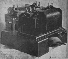
The high frequency exhibit embraced Mr. Tesla's first original apparatus used in his investigations. There was exhibited a glass tube with one layer of silk covered wire wound at the top and a copper ribbon on the inside. This was the first disruptive discharge coil constructed by him. At U is shown the disruptive discharge coil exhibited by him in his lecture before the American Institute of Electrical Engineers, in May, 1891. At V and W are shown some of the first high frequency transformers. A number of various fields and armatures of small models of high frequency apparatus as shown at X and Y, and others not visible in the picture, were exhibited. In the annexed space the dynamo then used by Mr. Tesla at Columbia College was exhibited; also another form of high frequency dynamo used.
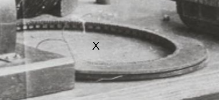
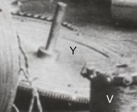
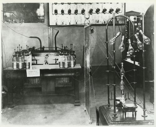
Fig 311
https://historicpittsburgh.org/islandora/object/pitt%3A20170323-hpichswp-0043
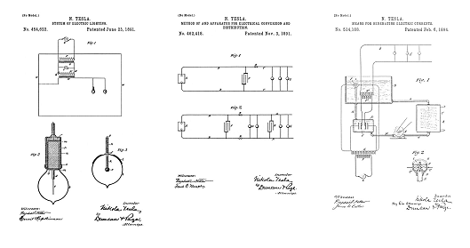
[- Insert Note: Left Front: Leyden Jars on a table. Left Rear: U.S. Patent 514,168, which is being used as the power supply in place of a high-frequency alternator used in Fig 125 - Right Front: Tesla Hairpin Circuit/Impedance Demonstration using Sawyer-Man stopper type incandescent lamps. Right Rear: Annex Marble Switchboard - A close examination of the archived image using the viewer link shows these demonstrations were photographed while in low power operation. The Leyden jars on the table, left, are divided into two equal values and there is a running rotary spark gap placed between the two banks of jars. The output of this oscillator is illuminating some of the bulbs in the hairpin circuit impedance demonstration. -]
In this space also was arranged a battery of Leyden jars and his large disruptive discharge coil which was used for exhibiting the light phenomena in the adjoining dark room. The coil was operated at only a small fraction of it's capacity, as the necessary condensers and transformers could not be had and as Mr. Tesla's stay was limited to one week; notwithstanding, the phenomena were of a striking character. In the room were arranged two large plates placed at a distance of about eighteen feet from each other. Between them were placed two long tables with all sorts of phosphorescent bulbs and tubes; many of these were prepared with great care and marked legibly with the names which would shine with phosphorescent glow. Among them were some with the names of Helmholtz, Faraday, Maxwell, Henry, Franklin, etc. Mr. Tesla had also not forgotten the greatest living poet of his own country, Zmaj Jovan; two or three were prepared with inscriptions like "Welcome Electricians" and produced a beautiful effect. Each represented some phase of his work and stood for some individual experiment of importance. Outside the room was the small battery seen in Fig 311, for exhibition of some of the impedance and other phenomena of interest. Thus, for instance, a thick copper bar bent in arched form was provided with clamps for the attachment of lamps, and a number of lamps were kept at incandescence on the bar; there was also a little motor shown on the table operated by disruptive discharge.
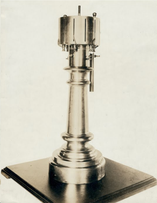
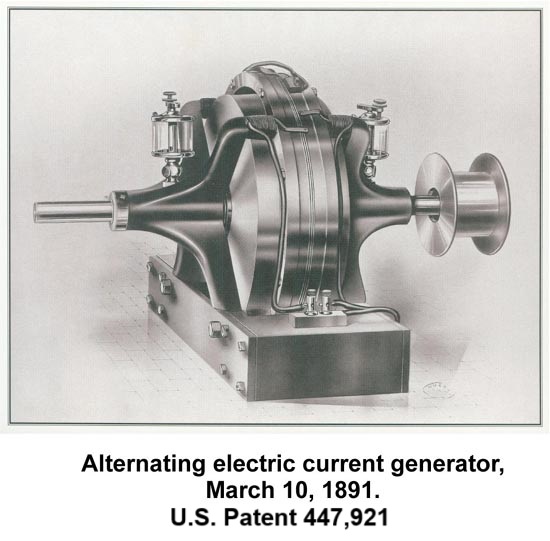
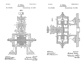
514,169 - Reciprocating Engine - Photographed at Tesla's World's Fair Exhibit
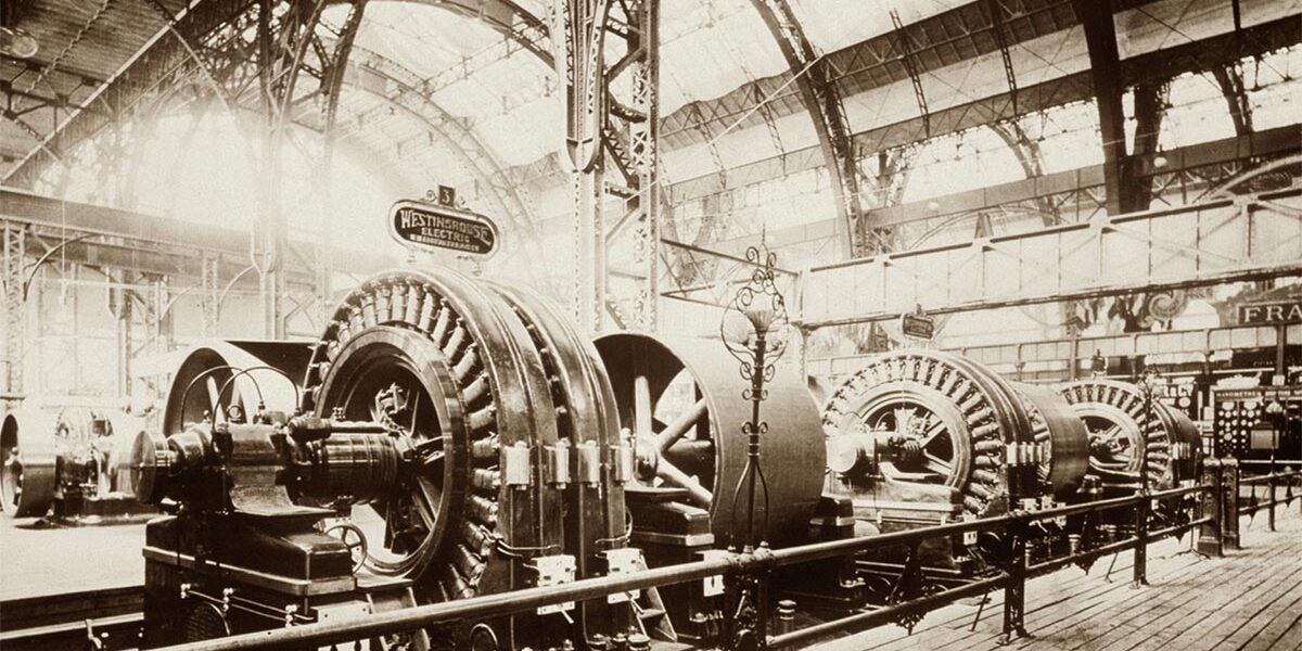
As will be remembered by those who visited the Exposition, the Westinghouse Company made a fine exhibit of the various commerical motors of the Tesla system, while the twelve generators in Machinery Hall were of the two-phase type constructed for distributing light and power. Mr. Tesla also exhibited some models of his oscillators.
Previous Chapter --- Contents --- Next Chapter
* - Editor's Bold
Machinery Hall + Electricity Building
Click for higher resolution image courtesy of the Paul V. Gavin Library
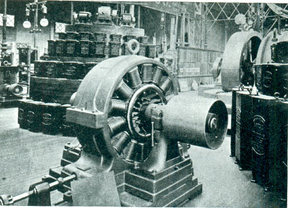
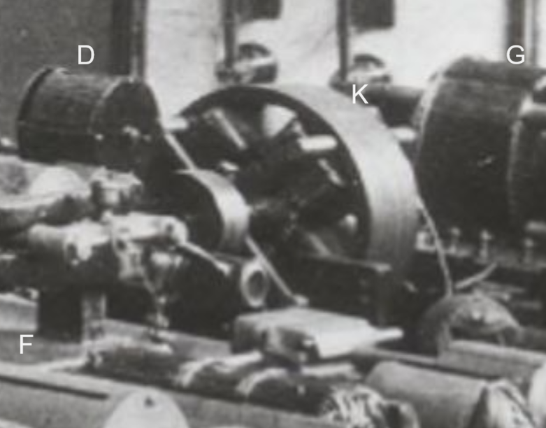
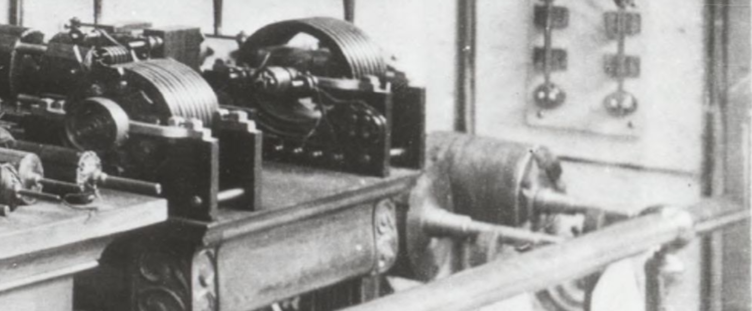
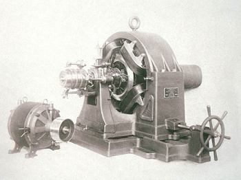
Westinghouse production line 100 HP synchronous Tesla Motor/Generator on display in the Electricity Building.
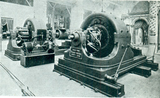
Front right: Westinghouse production line 500 HP Tesla 2-phase motor: Note the armature Tesla designed, a modification of the armature shown in Fig 305 above. - To the left of the large motor is a demonstration showing a benchtop, Tesla designed, Westinghouse manufactured, 2-phase motor directly shaft coupled and driving another rotational machine, possibly 447,921. The drive motor is a heavier duty, larger clone of the motor "N" above - Tesla had a nearly identical setup in his laboratory, with a nearly identical motor and coupler, driven by the isochronous generator he demonstrated at the Fair. The frequency locked motor powered rotating devices used in both transmitter and receiver research. - To the far left is a Tesla designed Westinghouse manufactured rotary transformer or rotary converter. These rotational machines were used for high demand DC current applications like electric railways and bauxite smelting before mercury or silicon rectification was available. This photo was taken in the Westinghouse exhibit in the Electricity Building.
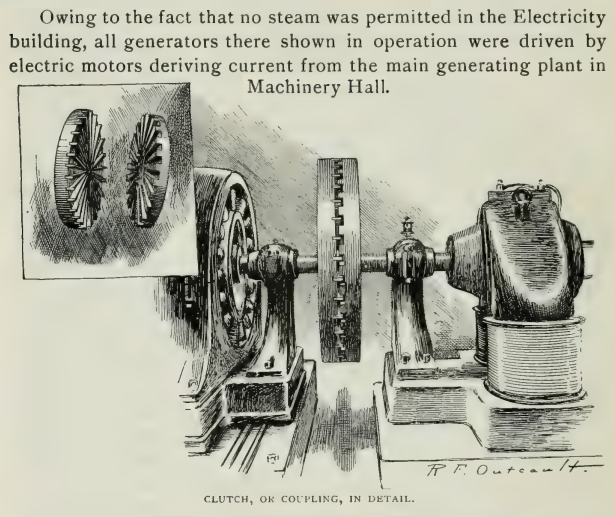
This image and the exhibit photo above taken in the Electricity Building show exactly how Tesla set up and operated the high-frequency alternators 447,920 - and - 447,921, and their predecessor equipment such as "X" and "Y" photographed above, for wireless research. The power supply used to drive the phase motor was the isochronous generator, U.S. Patent 511,916 that was demonstrated at the Fair. Similar arrangements were used to drive circuit controllers, rotational receivers, rotary spark gaps, etc.. in synchronism. At one point Tesla used the setup above, with two identical synchronous motors facing each other, and instead of a coupler, two rotary spark gap disks were rotated in opposite directions. See: Circuit Controllers.
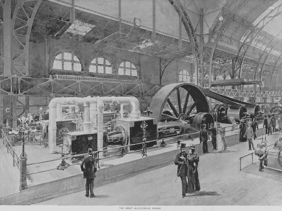
This was the end of the "War of the Currents" between Westinghouse/Tesla-Polyphase and Edison/General Electric. The DC generators in the Electricity Building that were displayed by General Electric were all driven by Tesla patented motors on his 2-phase system, current supplied by Westinghouse manufactured 2-phase alternators. A variety of engines were employed, but the majority of horsepower was produced by Westinghouse steeple engines of a new design. There were people who accused Westinghouse of underbidding to secure the lighting contract from the fair organization. But small organizations and companies who leased space in the Fair buildings went to Westinghouse directly to have electric light "spectaculars" installed in their exhibit spaces, and other companies ran demonstrations using line-shaft equipment, and those exhibits were Westinghouse powered separately from the fair lighting. The contracts with private vendors and organizations, including General Electric, made providing the power and lights to the Fair a very lucrative endeavor. More than half of the installed generator capacity went to meet private demand that was contracted separately and was not paid for by the fair organization.
This also marks the turning point in Tesla's development of wireless. Tesla did not attempt to scale up his high-frequency alternators. By the time Tesla demonstrated the high-frequency alternators 447,920 -&- 447,921 in 1891, he was filing patents on electrical oscillators with two-terminal outputs, and no further alternator work was recorded. By 1893, and the World's Fair, Tesla was demonstrating the circuit shown in Figure 125 using the electrical oscillator patent photographed above, U.S. Patent 514,168, as the power supply. Rather than attempt to scale up the shaft-driven alternators: Tesla realized it would be much simpler, easier, and cheaper, to use the system he himself had described, and was now advanced to industrial scale, to drive a powerful oscillator: rather than scale up high-frequency alternators to industrial size and power output levels. Efficiency and frequency stability problems were much easier to solve with an electrical oscillator research path and development.
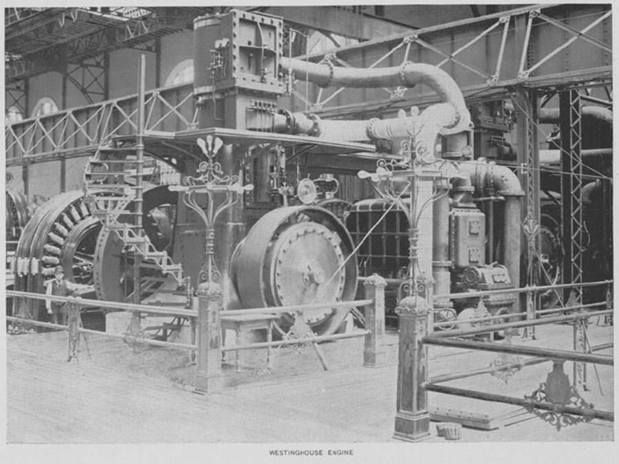
Westinghouse production line 1000 HP steam engine and 2-phase alternating current generator. Tesla and Albert Schmid designed the armature. US Patent 417,794. Click image for a higher resolution courtesy of the
Paul V. Gavin Library
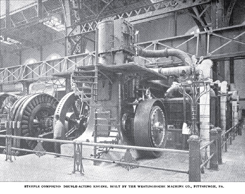
"While the Westinghouse Machine Company of Pittsburgh have at the Fair a number of their well-known "Junior," "Standard" and regular compound engines, the chief interest of their exhibit lies in six steeple-compound engines of an entirely new type recently developed by them, the engines being double and not single-acting like the other Westinghouse engines, and each being rated at 1ooo horse-power, which is the smallest size of this type to be turned out. The general and sectional views and the end elevation of one of these engines which accompany this paper clearly explain the main features of the design." -- 1893 Article-Westinghouse Machine Co., Steeple Compound Double Acting Steam Engine, Cassier's Magazine Sep 1893, pgs. 340-343, archived by http://vintagemachinery.org/
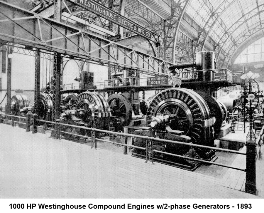
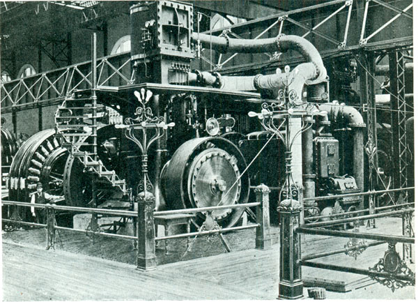
Row of Westinghouse production line 1000 HP engines w/2-phase generators.
Tesla and Albert Schmid designed these armatures: US Patent 417,794
Image Source:https://historicpittsburgh.org/islandora/object/pitt%3A20170323-hpichswp-0024
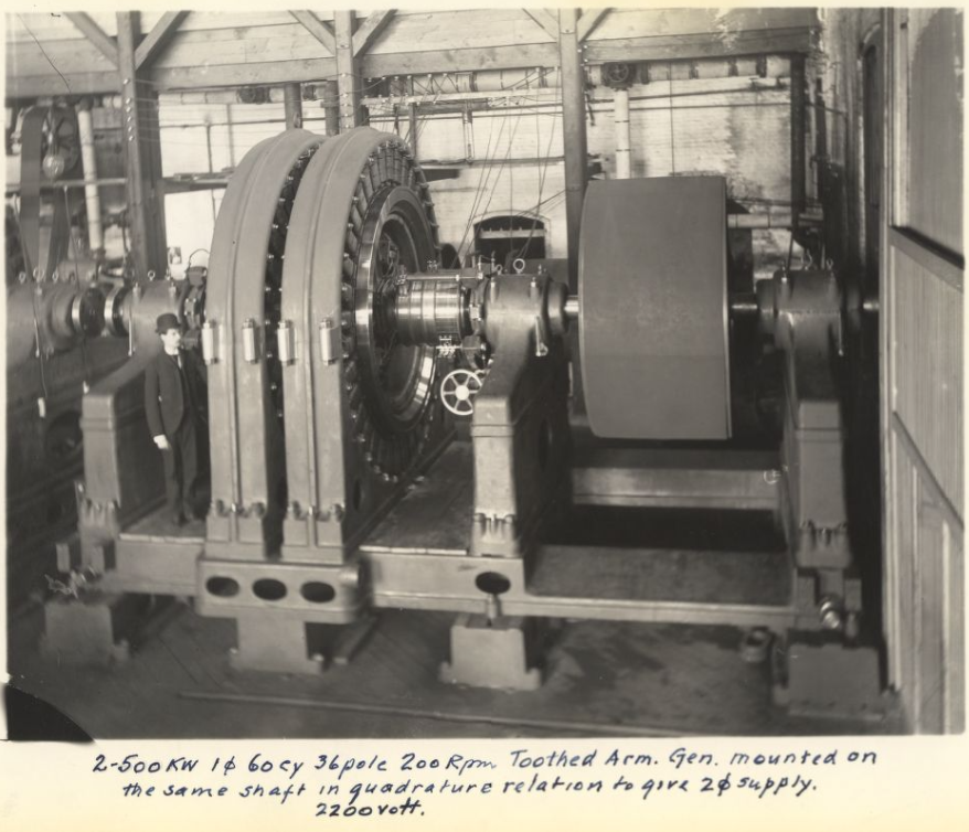
A man stands beside two 750 K.W. alternators at the World's Fair. Caption reads: "Chicago World's Fair, 1893. Two single-phase alternators magnetically coupled, 90 degrees electrically out of phase to provide two phase alternating current for exposition lighting." Image courtesy of:
https://historicpittsburgh.org/collection/westinghouse-electric-corporation-photographs
Production line Westinghouse alternator with toothed armature as shown in the patent referenced above. The armature coils are mounted inside of the rotating steel rim, with the laminated magnetic poles protruding from the surface. A great deal of thought and discussion went on between Albert Schmid and Nikola Tesla on the construction of these machines. Mass production demanded that the coils be assembly line wound, and then inserted into the armature frame. When Tesla left Westinghouse after his year of consulting work the industrial development project slowed. George Westinghouse had hired Benjamin Lamme and after training in house he was promoted and assigned the job of bringing in production on the 500 HP+ industrial scale machines. He was responsible for the final production design of these alternators, which had to be overspeed tested to ensure no premature failures occurred. It passed, and went into production. These were Tesla's brainchild, the initial 100 HP production designs and manufacture was done with Albert Schmid, then Charles F Scott was added, and then Benjamin Lamme basically took Tesla's place when he left. Benjamin's sister Bertha was a mechanical and electrical engineer and she was hired about this time to work on the Niagara Falls turbogenerator designs.
THE ELECTRICAL ENGINEER - A weekly magazine published in the 1890's, ran a short article on the Westinghouse power plant installation: Lighting the White City. They have poor quality images in the Google scan from the University of Virginia Library, but the text absolutely gives reference to the scope and scale. Sections of the completed installation are imaged above, the poor quality images in the article are of the construction phase.
LIGHTING THE WHITE CITY
The Electrical Engineer - Vol. XV. - April 26, 1893
Westinghouse Work at the Fair
The Electrical Engineer, August 16, 1893, Vol. XVI
The World's Fair in Retrospect
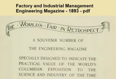
Factory and Industrial Management
The Engineering magazine
Internet Archive Project, 1052 pages with table of contents.
Tesla designed rotary transformer built by Westinghouse.
Tesla's Laboratory Power
Boiler, Steam Engine, Line-Shaft, Belts & Pulleys
A NEW SYSTEM OF ALTERNATE CURRENT MOTORS AND TRANSFORMERS
Paper by Nikola Tesla read to the American Institute of Electrical Engineers on May 16, 1888
Tesla's Cymatic Research
Steam Powered Isochronous Acoustic Oscillators & Generators
Nikola Tesla on Mechanical and Electrical Oscillators
Chapter XLIII - The Martin Book
Tesla's Electrical Isochronous Oscillators
Capacitive Discharge Power Processing
Articles by Tesla
Tesla made public disclosures of means, methods, systems, and apparatus in various articles.
To the Archive Page Discussion on Tesla's Technology