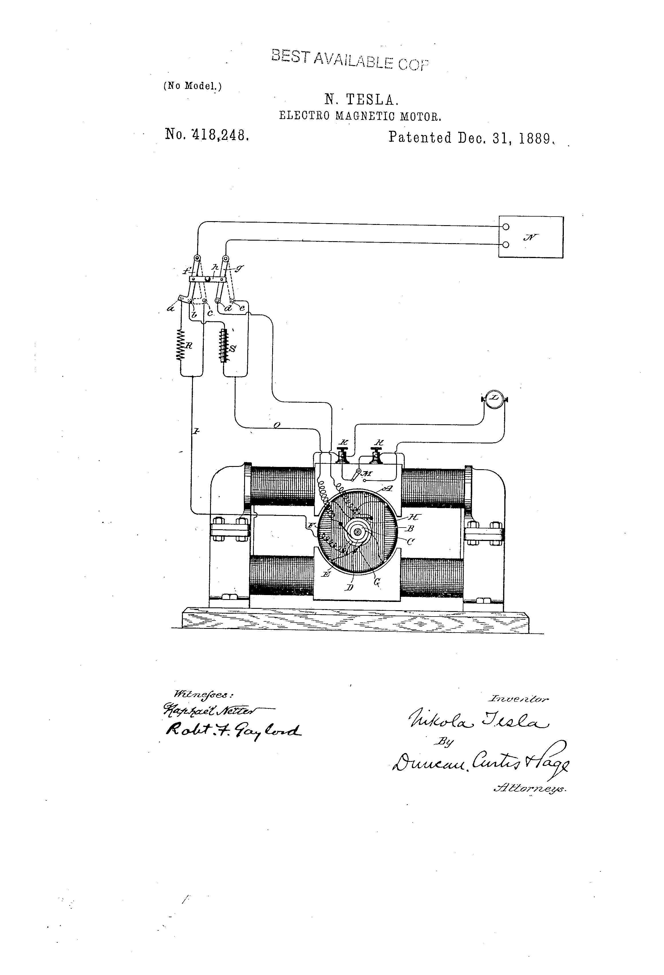
418,248
ELECTRO-MAGNETIC MOTOR - May 20, 1889
UNITED STATES PATENT OFFICE
NIKOLA TESLA, OF NEW YORK, N. Y., ASSIGNOR TO THE TESLA ELECTRIC COMPANY, OF SAME PLACE
Nikola Tesla Patent 418,248 ELECTRO-MAGNETIC MOTOR
SPECIFICATION forming part of Letters Patent No. 418,248, dated December 31, 1889
Application filed May 20, 1889. Serial No. 311,420. (No model.)
To all whom it may concern:
Be it known that I, NIKOLA TESLA, a subject of the Emperor of Austria-Hungary, formerly of Smiljan, Lika, border country of Austria-Hungary, but now residing at New York, in the county and State of New York, have invented certain new and useful Improvements in Methods of Operating Electro-Magnetic Motors, of which the following is a specification, reference being had to the drawing accompanying and forming a part of the same.
In a patent granted to me April 16, 1889, No. 401,520, I have shown and described a method of operating alternating-current motors by first shifting or rotating their magnetic poles until they had reached or passed a synchronous speed and then alternating the poles, or, in other words, by transforming the motor by a change of circuit-connections from one operated by the action of two or more independent energizing-currents to a motor operated by a single current or several acting as one.
The present invention is a specific way of carrying out the same invention; and it consists in the following method: On the start I progressively shift the magnetic poles of one element or field of the motor by alternating currents differing in phase as passed through independent energizing-circuits and short-circuit the coils of the other element. When the motor thus started reaches or passes the limit of speed synchronous with the generator, I connect up the coils previously short-circuited with a source of direct current and by a change of the circuit-connections produce a simple alternation of the poles. The motor then continues to run in synchronism with the generator. There are many specifically-different ways in which this may be carried out, but I have selected one for illustrating the principle. This is illustrated in the annexed drawing, which is a side view of a motor with a diagram of the circuits and devices used in the system.
The motor shown is one of the ordinary forms, with field-cores either laminated or solid and with a cylindrical laminated armature wound, for example, with the coils A B at right angles. The shaft of the armature carries three collecting or contact rings C D E. (Shown, for better illustration, as of different diameters.)
One end of coil A connects to one ring, as C, and one end of coil B connects with ring D. The remaining ends are connected to ring E. Collecting springs or brushes F G H bear upon the rings and lead to the contacts of a switch, to be hereinafter described. The field-coils have their terminals in binding-posts K K, and may be either closed upon themselves or connected with a source of direct current L by means of a switch M. The main or controlling switch has five contacts a b c d e and two levers f g, pivoted and connected by an insulating cross-bar h, so as to move in parallelism. These levers are connected to the line-wires from a source of alternating currents N. Contact a is connected to brush G and coil B through a dead-resistance R and wire P. Contact b is connected with brush F and coil A through a self-induction coil S and wire O. Contacts c and e are connected to brushes G F, respectively, through the wires P O, and contact d is directly connected with brush H. The lever f has a widened end which may span the contacts a b. When in such position and with lever g on contact d, the alternating currents divide between the two motor-coils, and by reason of their different self-induction a difference of current-phase is obtained that starts the motor in rotation. In starting, as I have above stated, the field-coils are short-circuited.
When the motor has attained the desired speed, the switch is shifted to the position shown in dotted lines—that is to say, with the levers f g resting on points c e. This connects up the two armature-coils in series, and the motor will then run as a synchronous-motor. The field-coils are thrown into circuit with the direct-current source when the main switch is shifted.
What I claim herein as my invention is—
1. The method of operating electro-magnetic motors, which consists in first progressively shifting or rotating the magnetic poles of one element until it has reached a synchronous speed and then alternating said poles and passing a direct current through the coils of the other element, as herein set forth.
2. The method of operating electro-magnetic motors, which consists in short-circuiting the coils of one element, as the field-magnet, and passing through the energizing-coils of the other element, as the armature, alternating currents differing in phase, and then, when the motor has attained a given speed, passing through the field-coils a direct current and through the armature-coils alternating currents coinciding in phase.
NIKOLA TESLA
Click image for higher-resolution
Source File: US Patent 418,248 - pdf
Chapter IX - The Martin Book
Change From Double Current to Single Current Motor
Thomas Commerford Martin
A description is given elsewhere of a method of operating alternating current motors by first rotating their magnetic poles until they have attained synchronous speed, and then alternating the poles. The motor is thus transformed, by a simple change of circuit connections from one operated by the action of two or more independent energizing currents to one operated either by a single current or by several currents acting as one. Another way of doing this will now be described.
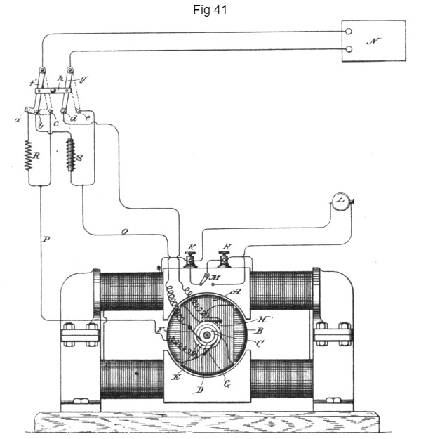
At the start the magnetic poles of one element or field of the motor are progressively shifted by alternating currents differing in phase and passed through independent energizing circuits, and short circuit the coils of the other element. When the motor thus started reaches or passes the limit of speed synchronous with the generator, Mr. Tesla connects up the coils previously short-circuited with a source of direct current and by a change of the circuit connections produces a simple alternation of the poles. The motor then continues to run in synchronism with the generator. The motor here shown in Fig. 41 is one of the ordinary forms, with field-cores either laminated or solid and with a cylindrical laminated armature wound, for example, with the coils A B at right angles. The shaft of the armature carries three collecting or contact rings C D E. (Shown, for better illustration, as of different diameters.)
One end of coil A connects to one ring, as C, and one end of coil B connects with ring D. The remaining ends are connected to ring E. Collecting springs or brushes F G H bear upon the rings and lead to the contacts of a switch, to be presently described. The field-coils have their terminals in binding-posts K K, and may be either closed upon themselves or connected with a source of direct current L, by means of a switch M. The main or controlling switch has five contacts a b c d e and two levers f g, pivoted and connected by an insulating cross-bar h, so as to move in parallelism. These levers are connected to the line wires from a source of alternating currents N. Contact a is connected to brush G and coil B through a dead resistance R and wire P. Contact b is connected with brush F and coil A through a self-induction coil S and wire O. Contacts c and e are connected to brushes G F, respectively, through the wires P O, and contact d is directly connected with brush H. The lever f has a widened end, which may span the contacts a b. When in such position and with lever g on contact d, the alternating currents divide between the two motor-coils, and by reason of their different self-induction a difference of current-phase is obtained that starts the motor in rotation. In starting, the field-coils are short circuited.
When the motor has attained the desired speed, the switch is shifted to the position shown in dotted lines—that is to say, with the levers f g resting on points c e. This connects up the two armature coils in series, and the motor will then run as a synchronous motor. The field-coils are thrown into circuit with the direct current source when the main switch is shifted.
Previous Chapter --- Contents --- Next Chapter
To the Archive Page Discussion on Tesla's Technology
Lab-Tesla disclosures on the technology just presented
A NEW SYSTEM OF ALTERNATE CURRENT MOTORS AND TRANSFORMERS
Paper by Nikola Tesla read to the American Institute of Electrical Engineers on May 16, 1888
EXPERIMENTS WITH ALTERNATE CURRENTS OF VERY HIGH FREQUENCY AND THEIR APPLICATION TO METHODS OF ARTIFICIAL ILLUMINATION