433,700
ALTERNATING-CURRENT ELECTRO-MAGNETIC MOTOR - May 26, 1890
UNITED STATES PATENT OFFICE
NIKOLA TESLA, OF NEW YORK, N. Y., ASSIGNOR TO THE TESLA ELECTRIC COMPANY, OF SAME PLACE
Nikola Tesla Patent 433,700 ALTERNATING-CURRENT ELECTRO-MAGNETIC MOTOR
SPECIFICATION forming part of Letters Patent No. 433,700, dated August 5, 1890
Application filed May 26, 1890. Serial No. 345,388. (No model.)
To all whom it may concern:
Be it known that I, NIKOLA TESLA, a subject of the Emperor of Austria-Hungary, from Smiljan, Lika, border country of Austria-Hungary, residing at New York, in the county and State of New York, have invented certain new and useful Improvements in Alternating-Current Electro-Magnetic Motors, of which the following is a specification, reference being had to the drawings accompanying and forming a part of the same.
This invention is an improvement in that class of electro-magnetic motors in which the rotation is produced by the progressive movement or effect of the maximum magnetic points or poles produced by the conjoint action or effect of two energizing-circuits through which are passed alternating currents, or currents of rapidly-varying strength of a kindred nature.
The improvements subject of this application are more particularly applicable to that class of motors in which two or more sets of energizing-magnets are employed, and in which by artificial means a certain interval of time is made to elapse between the respective maximum or minimum periods or phases of their magnetic attraction or effect. This interval or difference in phase between the two sets of magnets, when artificially produced, is limited in extent. It is desirable, however, for the economical working of such motors that the strength or attraction of one set of magnets should be maximum at the time when that of the other set is minimum and conversely; but these conditions have not heretofore been realized except in cases where the two currents have been obtained from independent sources in the same or different machines.
The object of the present invention is to establish conditions more nearly approaching the theoretical requirements of perfect working, or, in other words, to produce artificially a difference of magnetic phase by means of a current from a single primary source sufficient in extent to meet the requirements of practical and economical working.
In carrying out my invention I employ a motor with two sets of energizing or field magnets, each wound with coils connected with a source of alternating or rapidly-varying currents, but forming two separate paths or circuits. The magnets of one set I protect to a certain extent from the energizing action of the current by means of a magnetic shield or screen interposed between the magnet and its energizing-coil. This shield is properly adapted to the conditions of particular cases, so as to shield or protect the main core from magnetization until it has become itself saturated and no longer capable of containing all the lines of force produced by the current. By this means it will be seen that the energizing action begins in the protected set of magnets a certain arbitrarily-determined period of time later than in the other, and that by this means alone or in conjunction with other means or devices heretofore employed a practically-economical difference of magnetic phase may readily be secured.
The nature and operation of the invention will be more fully explained by reference to the accompanying drawings.
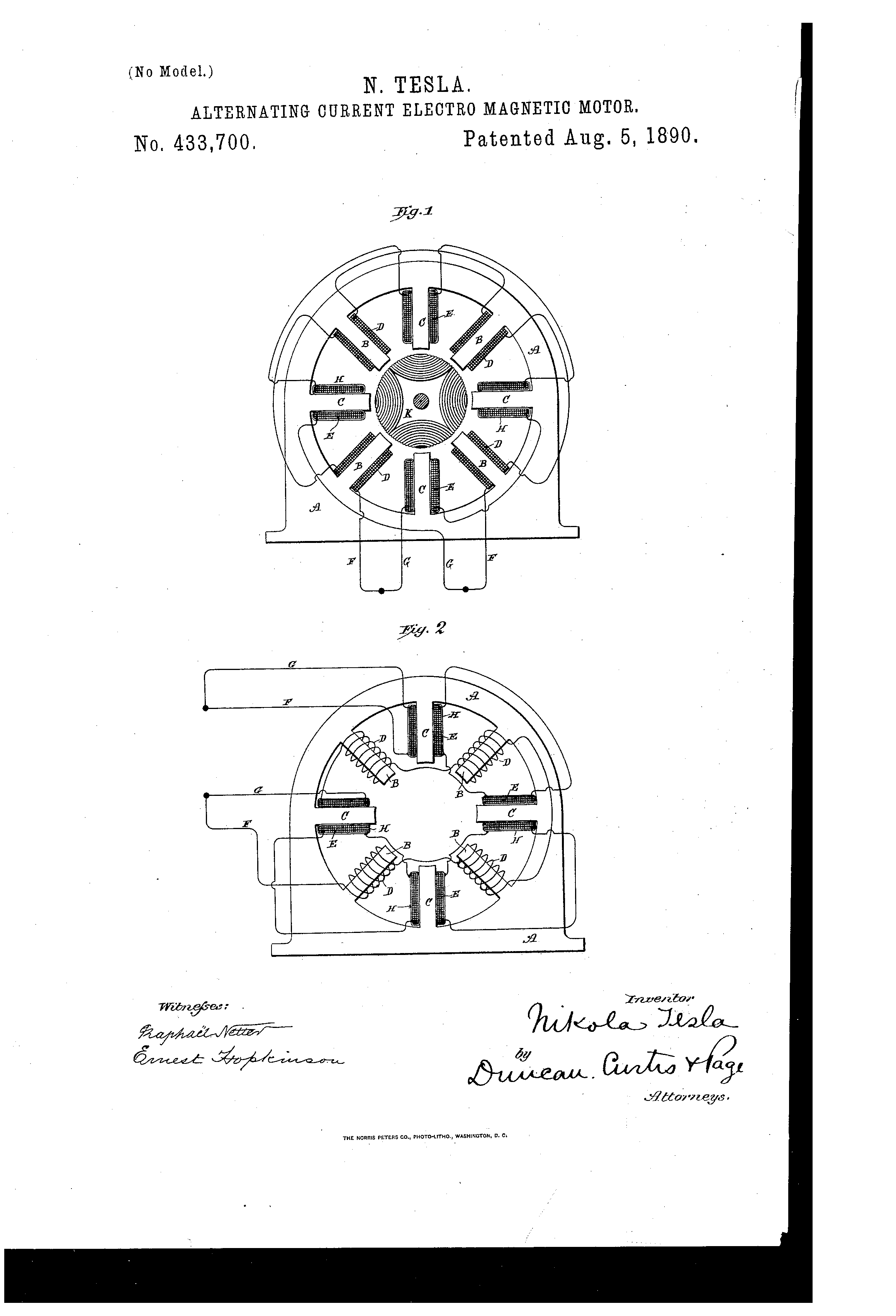
Figure 1 is a view of a motor, partly in section, with a diagram illustrating the invention. Fig. 2 is a similar view of a modification of the same.
In Fig. 1, which exhibits the simplest form of the invention, A A is the field-magnet of a motor, having, say, eight poles or inwardly-projecting cores B and C. The cores B form one set of magnets and are energized by coils D. The cores C, forming the other set, are energized by coils E, and the coils are connected, preferably, in series with one another, in two derived or branched circuits F G, respectively, from a suitable source of current. Each coil E is surrounded by a magnetic shield H, which is preferably composed of an annealed, insulated, or oxidized iron wire wrapped or wound on the coils in the manner indicated, so as to form a closed magnetic circuit around the coils and between the same and the magnetic cores C. Between the pole pieces or cores B C is mounted the armature K, which, as is usual in this type of machines, is wound with coils L closed upon themselves. The operation resulting from this disposition is as follows: If a current impulse be directed through the two circuits of the motor, it will quickly energize the cores B, but not so the cores C, for the reason that in passing through the coils E there is encountered the influence of the closed magnetic circuits formed by the shields H. The first effect is to effectively retard the current impulse in circuit G, while at the same time the proportion of current which does pass does not magnetize the cores C, which are shielded or screened by the shields H. As the increasing electro-motive force then urges more current through the coils E, the iron wire H becomes magnetically saturated and incapable of carrying all the lines of force, and hence ceases to protect the cores C, which become magnetized, developing their maximum effect after an interval of time subsequent to the similar manifestation of strength in the other set of magnets, the extent of which is arbitrarily determined by the thickness of the shield H, and other well-understood conditions.
From the above it will be seen that the apparatus or device acts in two ways. First, by retarding the current, and, second, by retarding the magnetization of one set of the cores, from which its effectiveness will readily appear.
Many modifications of the principle of this invention are possible. One useful and efficient application of the invention is shown in Fig. 2. In said figure a motor is shown similar in all respects to that above described, except that the iron wire H, which is wrapped around the coils E, is in this case connected in series with the coils D. The iron-wire coils H, are connected and wound, so as to have little or no self-induction, and being added to the resistance of the circuit F the action of the current in that circuit will be accelerated, while in the other circuit G it will be retarded. The shield H may be made in many forms, as will be understood, and used in different ways, as appears from the foregoing description. I do not, however, limit myself to any specific form or arrangement; but
What I claim is—
1. In an alternating-current motor having two energizing-circuits, the combination, with the magnetic cores and coils of one of the circuits, of interposed magnetic shields or screens for retarding the magnetization of said cores, as set forth.
2. In an alternating-current motor having two energizing-circuits, the combination, with the magnetic cores and the coils of one of the circuits wound thereon, of magnetic shields or coils wound around said coils at right angles to their convolutions, as set forth.
3. In an alternating-current motor having two energizing-circuits, the combination, with the magnetic cores and the coils of one of the circuits which energize the said cores, of magnetic shields forming closed magnetic circuits around the coils and interposed between the coils and cores, as set forth.
4. In an alternating-current motor having two energizing-circuits derived from the same source, the combination, with the cores and the coils of one of the circuits that energizes the same, of insulated iron-wire coils wound on the said energizing-coils at right angles to their convolutions and connected up in series with the coils of the other energizing-circuit, as set forth.
NIKOLA TESLA
Click image for higher-resolution
Source File: US Patent 433,700 - pdf
Chapter XIII - The Martin Book
Method of Obtaining Difference of Phase by Magnetic Shielding
Thomas Commerford Martin
In that class of motors in which two or more sets of energizing magnets are employed, and in which by artificial means a certain interval of time is made to elapse between the respective maximum or minimum periods or phases of their magnetic attraction or effect, the interval or difference in phase between the two sets of magnets is limited in extent. It is desirable, however, for the economical working of such motors that the strength or attraction of one set of magnets should be maximum, at the time when that of the other set is minimum, and conversely; but these conditions have not heretofore been realized except in cases where the two currents have been obtained from independent sources in the same or different machines. Mr. Tesla has therefore devised a motor embodying conditions that approach more nearly the theoretical requirements of perfect working, or in other words, he produces artificially a difference of magnetic phase by means of a current from a single primary source sufficient in extent to meet the requirements of practical and economical working. He employs a motor with two sets of energizing or field magnets, each wound with coils connected with a source of alternating or rapidly-varying currents, but forming two separate paths or circuits. The magnets of one set are protected to a certain extent from the energizing action of the current by means of a magnetic shield or screen interposed between the magnet and its energizing coil. This shield is properly adapted to the conditions of particular cases, so as to shield or protect the main core from magnetization until it has become itself saturated and no longer capable of containing all the lines of force produced by the current. It will be seen that by this means the energizing action begins in the protected set of magnets a certain arbitrarily-determined period of time later than in the other, and that by this means alone or in conjunction with other means or devices heretofore employed a practical difference of magnetic phase may readily be secured.
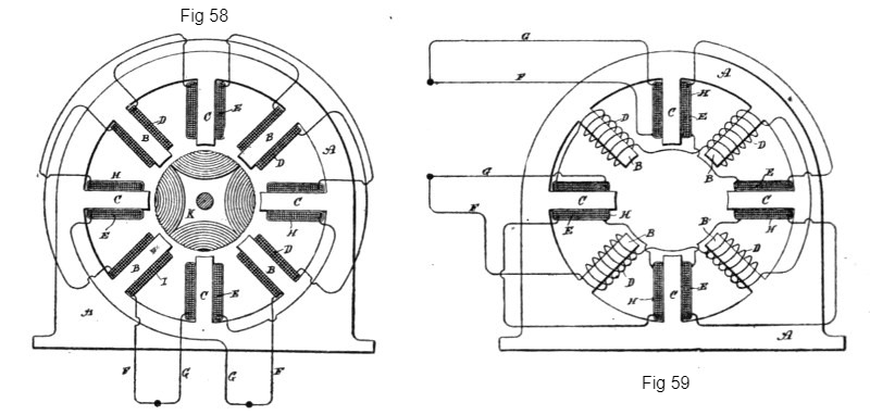
Fig. 58 is a view of a motor, partly in section, with a diagram illustrating the invention. Fig. 59 is a similar view of a modification of the same.
In Fig. 58, which exhibits the simplest form of the invention, A A is the field-magnet of a motor, having, say, eight poles or inwardly-projecting cores B and C. The cores B form one set of magnets and are energized by coils D. The cores C, forming the other set are energized by coils E, and the coils are connected, preferably, in series with one another, in two derived or branched circuits, F G, respectively, from a suitable source of current. Each coil E is surrounded by a magnetic shield H, which is preferably composed of an annealed, insulated, or oxidized iron wire wrapped or wound on the coils in the manner indicated so as to form a closed magnetic circuit around the coils and between the same and the magnetic cores C. Between the pole pieces or cores B C is mounted the armature K, which, as is usual in this type of machines, is wound with coils L closed upon themselves. The operation resulting from this disposition is as follows: If a current impulse be directed through the two circuits of the motor, it will quickly energize the cores B, but not so the cores C, for the reason that in passing through the coils E there is encountered the influence of the closed magnetic circuits formed by the shields H. The first effect is to retard effectively the current impulse in circuit G, while at the same time the proportion of current which does pass does not magnetize the cores C, which are shielded or screened by the shields H. As the increasing electromotive force then urges more current through the coils E, the iron wire H becomes magnetically saturated and incapable of carrying all the lines of force, and hence ceases to protect the cores C, which becomes magnetized, developing their maximum effect after an interval of time subsequent to the similar manifestation of strength in the other set of magnets, the extent of which is arbitrarily determined by the thickness of the shield H, and other well-understood conditions.
From the above it will be seen that the apparatus or device acts in two ways. First, by retarding the current, and, second, by retarding the magnetization of one set of the cores, from which its effectiveness will readily appear.
Many modifications of the principle of this invention are possible. One useful and efficient application of the invention is shown in Fig. 59. In this figure a motor is shown similar in all respects to that above described, except that the iron wire H, which is wrapped around the coils E, is in this case connected in series with the coils D. The iron-wire coils H, are connected and wound, so as to have little or no self-induction, and being added to the resistance of the circuit F, the action of the current in that circuit will be accelerated, while in the other circuit G it will be retarded. The shield H may be made in many forms, as will be understood, and used in different ways, as appears from the foregoing description.
As a modification of his type of motor with "shielded" fields, Mr. Tesla has constructed a motor with a field-magnet having two sets of poles or inwardly-projecting cores and placed side by side, so as practically to form two fields of force and alternately disposed—that is to say, with the poles of one set or field opposite the spaces between the other. He then connects the free ends of one set of poles by means of laminated iron bands or bridge-pieces of considerably smaller cross-section than the cores themselves, whereby the cores will all form parts of complete magnetic circuits. When the coils on each set of magnets are connected in multiple circuits or branches from a source of alternating currents, electromotive forces are set up in or impressed upon each circuit simultaneously; but the coils on the magnetically bridged or shunted cores will have, by reason of the closed magnetic circuits, a high self-induction, which retards the current, permitting at the beginning of each impulse but little current to pass. On the other hand, no such opposition being encountered in the other set of coils, the current passes freely through them, magnetizing the poles on which they are wound. As soon, however, as the laminated bridges become saturated and incapable of carrying all the lines of force which the rising electromotive force, and consequently increased current, produce, free poles are developed at the ends of the cores, which, acting in conjunction with the others, produce rotation of the armature.
The construction in detail by which this invention is illustrated is shown in the accompanying drawings.
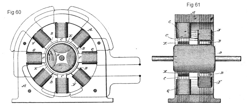
Fig. 60 is a view in side elevation of a motor embodying the principle. Fig. 61 is a vertical cross-section of the motor. A is the frame of the motor, which should be built up of sheets of iron punched out to the desired shape and bolted together with insulation between the sheets. When complete, the frame makes a field-magnet with inwardly projecting pole-pieces B and C. To adapt them to the requirements of this particular case these pole-pieces are out of line with one another, those marked B surrounding one end of the armature and the others, as C, the opposite end, and they are disposed alternately—that is to say, the pole-pieces of one set occur in line with the spaces between those of the other sets.
The armature D is of cylindrical form, and is also laminated in the usual way and is wound longitudinally with coils closed upon themselves. The pole-pieces C are connected or shunted by bridge-pieces E. These may be made independently and attached to the pole-pieces, or they may be parts of the forms or blanks stamped or punched out of sheet-iron. Their size or mass is determined by various conditions, such as the strength of the current to be employed, the mass or size of the cores to which they are applied, and other familiar conditions.
Coils F surround the pole-pieces B, and other coils G are wound on the pole-pieces C. These coils are connected in series in two circuits, which are branches of a circuit from a generator of alternating currents, and they may be so wound, or the respective circuits in which they are included may be so arranged, that the circuit of coils G will have, independently of the particular construction described, a higher self-induction than the other circuit or branch.
The function of the shunts or bridges E is that they shall form with the cores C a closed magnetic circuit for a current up to a predetermined strength, so that when saturated by such current and unable to carry more lines of force than such a current produces they will to no further appreciable extent interfere with the development, by a stronger current, of free magnetic poles at the ends of the cores C.
In such a motor the current is so retarded in the coils G, and the manifestation of the free magnetism in the poles C is so delayed beyond the period of maximum magnetic effect in poles B, that a strong torque is produced and the motor operates with approximately the power developed in a motor of this kind energized by independently generated currents differing by a full quarter phase.
Previous Chapter --- Contents --- Next Chapter
To the Archive Page Discussion on Tesla's Technology

Lab-Tesla disclosures on the technology just presented
A NEW SYSTEM OF ALTERNATE CURRENT MOTORS AND TRANSFORMERS
Paper by Nikola Tesla read to the American Institute of Electrical Engineers on May 16, 1888
EXPERIMENTS WITH ALTERNATE CURRENTS OF VERY HIGH FREQUENCY AND THEIR APPLICATION TO METHODS OF ARTIFICIAL ILLUMINATION