447,920
Method of Operating Arc Lamps - Oct 1, 1890
UNITED STATES PATENT OFFICE
NIKOLA TESLA, OF NEW YORK, N. Y.
Nikola Tesla Patent 447,920 METHOD OF OPERATING ARC-LAMPS
SPECIFICATION forming part of Letters Patent No. 447,920, dated March 10, 1891.
Application filed October 1, 1890. Serial No. 366,734. (No model.)
To all whom it may concern:
Be it known that I, NIKOLA TESLA, a subject of the Emperor of Austria-Hungary, residing at New York, in the county and State of New York, have invented certain new and useful Improvements in Methods of Operating Arc Lamps, of which the following is a specification.
This invention consists in an improved method of operating electric-arc lamps which are supplied with alternating or pulsating currents.
It has now become a common practice to run arc lamps by alternating or pulsating as distinguished from continuous currents; but an objection to such systems exists in the fact that the arcs emit a pronounced sound, varying with the rate of the alternations or pulsations of current, but under any circumstances constituting an objectionable and disagreeable feature, for which heretofore no effective remedy has been found or proposed. This noise is probably due to the rapidly alternating heating and cooling and consequent expansion and contraction of the gaseous matter forming the arc which corresponds with the periods or impulses of the current, for I have succeeded in abating it and producing quiet and smoothly-acting lamps by increasing, per unit of time, the number of alternations or pulsations of the current producing the arc to such an extent that the rate of the vibrations or changes in the arc producing the noise approximately equals or exceeds that which is generally regarded as the limit of audition. For example, I may use a generator which produces ten thousand or more alternations of current per second. In such a case the periodical heating and cooling of the arc would occur with such rapidity as to produce little or no perceptible effect upon the ear.
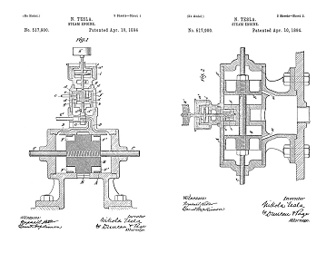
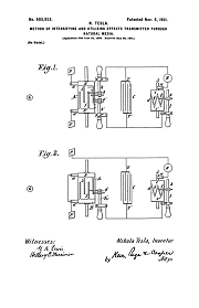
There are a number of ways in which the current may be varied at a rate exceeding the limit of audition, but probably the most practicable known to me at present is by the use of an alternating-current generator with a large number of poles and specially constructed for the purpose. Such a generator, for the purpose of the illustration of this case, I have shown in the accompanying drawings.
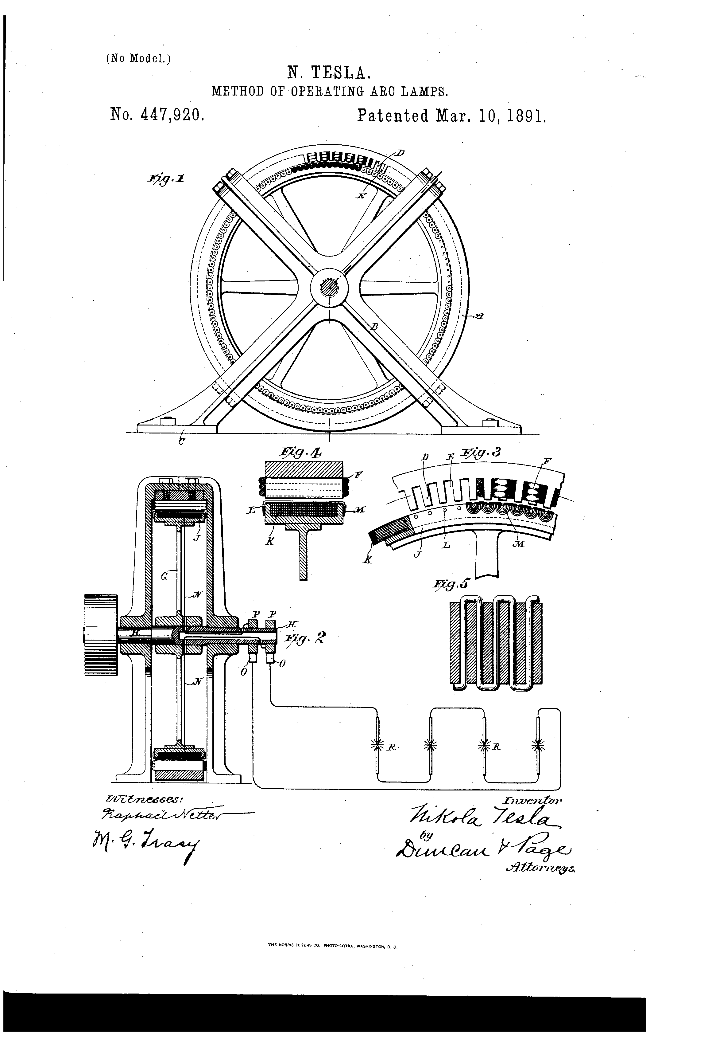
Figure 1 is a view of the generator in side elevation. Fig. 2 is a vertical cross-section of the same with a diagram of the circuit-connections. Fig. 3 is an enlarged view, in side elevation, of a part of the machine. Fig. 4 is an enlarged sectional detail of the armature and field. Fig. 5 is a detail section of the field-magnets exhibiting the plan of winding.
A is an annular magnetic frame supported by the cross-bars or brackets B, provided with feet C, upon which the machine rests. The interior of the annulus A is provided with a large number of projections or pole-pieces D. These may be formed or applied in a variety of ways—as, for example, by milling transverse grooves E.
Owing to the very large number and small size of the poles and the spaces between them, I apply the exciting or field coils by winding an insulated conductor F zigzag through the grooves, as shown in Fig. 5, carrying said wire around the annulus to form as many layers as is desired. In this way the pole-pieces D will be energized with alternately opposite polarity around the entire ring.
For the armature I employ a spider or circular frame G on a driving-shaft H, mounted in bearings in the brackets B. This spider carries a ring J, turned down, except at its edges, to form a trough-like receptacle for a mass of fine annealed iron wires K, which are wound in the groove to form the core proper for the armature-coils. Pins L are set in the sides of the ring J, and the coils M are wound over the periphery of the armature-structure and around the pins. The coils M are connected together in series, and these terminals N carried through the hollow shaft H to contact-rings P P, from whence the currents are taken off by brushes O. In this way a machine with a very large number of poles may be constructed. It is easy, for instance, to obtain in this manner three hundred and seventy-five to four hundred poles in a machine that may be safely driven at a speed of fifteen hundred or sixteen hundred revolutions per minute, which will produce ten thousand or eleven thousand alternations of current per second. Arc lamps R R are shown in diagram as connected up in series with the machine in Fig. 2. If such a current be applied to running arc lamps, the sound produced by or in the arc becomes practically inaudible, for by increasing the rate of change in the current, and consequently the number of vibrations per unit of time of the gaseous material of the arc up to or beyond ten thousand or eleven thousand per second, or to what is regarded as the limit of audition, the sound due to such vibrations will not be audible. The exact number of changes or undulations necessary to produce this result will vary somewhat according to the size of the arc—that is to say, the smaller the arc the greater the number of changes that will be required to render it inaudible within certain limits. Of course, as the rate of alternations or undulations for a given size of arc becomes very high the sound produced is less perceptible, and hence for some purposes the actual limit of audition may only be approached, provided the sound be rendered practically inaudible.
Another advantage gained by increasing as above set forth the number of alternations is that the arc acts more like that produced by a continuous current, in that it is more persistent, owing to the fact that the time interval between undulations is so small that the gaseous matter cannot cool down so far as to increase very considerably in resistance.
I claim—
The method of abating or rendering inaudible the sound emitted by arc lamps supplied with or operated by an alternating or pulsating current by increasing the rate of such alternations or pulsations up to that of the limit of audition, as set forth.
NIKOLA TESLA
Source File: US Patent 447,920 - pdf
Chapter XXIX - The Martin Book
Nikola Tesla's Alternating Current Generators for High Frequency, in Detail
Thomas Commerford Martin
It has become a common practice to operate arc lamps by alternating or pulsating, as distinguished from continuous, currents; but an objection which has been raised to such systems exists in the fact that the arcs emit a pronounced sound, varying with the rate of the alternations or pulsations of current. This noise is due to the rapidly alternating heating and cooling, and consequent expansion and contraction, of the gaseous matter forming the arc, which corresponds with the periods or impulses of the current. Another disadvantageous feature is found in the difficulty of maintaining an alternating current arc in consequence of the periodical increase in resistance corresponding to the periodical working of the current. This feature entails a further disadvantage, namely, that small arcs are impracticable.
Theoretical considerations have led Mr. Tesla to the belief that these disadvantageous features could be obviated by employing currents of a sufficiently high number of alternations, and his anticipations have been confirmed in practice. These rapidly alternating currents render it possible to maintain small arcs which, besides, possess the advantages of silence and persistency. The latter quality is due to the necessarily rapid alternations, in consequence of which the arc has no time to cool, and is always maintained at a high temperature and low resistance.
At the outset of his experiments Mr. Tesla encountered great difficulties in the construction of high frequency machines. A generator of this kind is described here, which, though constructed quite some time ago, is well worthy of a detailed description. It may be mentioned, in passing, that dynamos of this type have been used by Mr. Tesla in his lighting researches and experiments with currents of high potential and high frequency, and reference to them will be found in his lectures elsewhere printed in this volume.
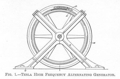
In the accompanying engravings, Figs. 199 and 200 show the machine, respectively, in side elevation and vertical cross-section; Figs. 201, 202 and 203 showing enlarged details of construction. As will be seen, A is an annular magnetic frame, the interior of which is provided with a large number of pole-pieces D.
Owing to the very large number and small size of the poles and the spaces between them, the field coils are applied by winding an insulated conductor F zigzag through the grooves, as shown in Fig. 203, carrying the wire around the annulus to form as many layers as is desired. In this way the pole-pieces D will be energized with alternately opposite polarity around the entire ring.
For the armature, Mr. Tesla employs a spider carrying a ring J, turned down, except at its edges, to form a trough-like receptacle for a mass of fine annealed iron wires K, which are wound in the groove to form the core proper for the armature-coils. Pins L are set in the sides of the ring J and the coils M are wound over the periphery of the armature-structure and around the pins. The coils M are connected together in series, and these terminals N carried through the hollow shaft H to contact-rings P P, from which the currents are taken off by brushes O.
In this way a machine with a very large number of poles may be constructed. It is easy, for instance, to obtain in this manner three hundred and seventy-five to four hundred poles in a machine that may be safely driven at a speed of fifteen hundred or sixteen hundred revolutions per minute, which will produce ten thousand or eleven thousand alternations of current per second. Arc lamps R R are shown in the diagram as connected up in series with the machine in Fig. 200. If such a current be applied to running arc lamps, the sound produced by or in the arc becomes practically inaudible, for, by increasing the rate of change in the current, and consequently the number of vibrations per unit of time of the gaseous material of the arc up to, or beyond, ten thousand or eleven thousand per second, or to what is regarded as the limit of audition, the sound due to such vibrations will not be audible. The exact number of changes or undulations necessary to produce this result will vary somewhat according to the size of the arc—that is to say, the smaller the arc, the greater the number of changes that will be required to render it inaudible within certain limits. It should also be stated that the arc should not exceed a certain length.
The difficulties encountered in the construction of these machines are of a mechanical as well as an electrical nature. The machines may be designed on two plans: the field may be formed either of alternating poles, or of polar projections of the same polarity. Up to about 15,000 alternations per second in an experimental machine, the former plan may be followed, but a more efficient machine is obtained on the second plan.
In the machine above described, which was capable of running two arcs of normal candle power, the field was composed of a ring of wrought iron 32 inches outside diameter, and about 1 inch thick. The inside diameter was 30 inches. There were 384 polar projections. The wire was wound in zigzag form, but two wires were wound so as to completely envelop the projections. The distance between the projections is about 3/16 inch, and they are a little over 1/16 inch thick. The field magnet was made relatively small so as to adapt the machine for a constant current. There are 384 coils connected in two series. It was found impracticable to use any wire much thicker than No. 26 B. and S. gauge on account of the local effects. In such a machine the clearance should be as small as possible; for this reason the machine was made only 1¼ inch wide, so that the binding wires might be obviated. The armature wires must be wound with great care, as they are apt to fly off in consequence of the great peripheral speed. In various experiments this machine has been run as high as 3,000 revolutions per minute. Owing to the great speed it was possible to obtain as high as 10 amperes out of the machine. The electromotive force was regulated by means of an adjustable condenser within very wide limits, the limits being the greater, the greater the speed. This machine was frequently used to run Mr. Tesla's laboratory lights. [ Continues in 447,921 ]
In the course of a very interesting article contributed to the Electrical World in February, 1891, Mr. Tesla makes some suggestive remarks on these high frequency machines and his experiences with them, as well as with other parts of the high frequency apparatus.
Previous Chapter --- Contents --- Next Chapter
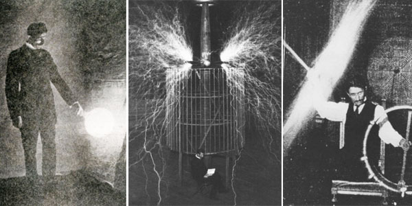
This machine was demonstrated by Nikola Tesla in his lecture: Experiments With Alternate Currents of Very High Frequency And Their Application To Methods of Articifical Illumination, May, 1891.
This patent is significant, there is discussion of this technology Here & Here
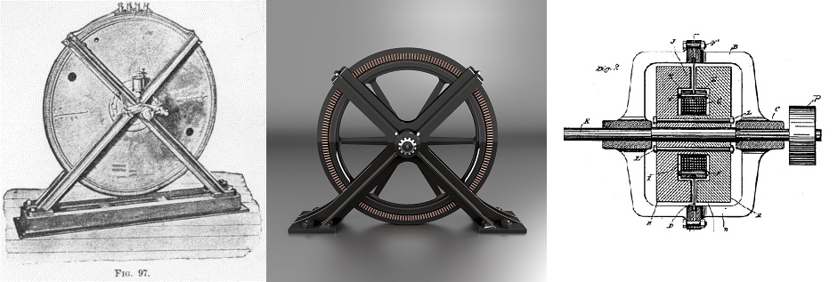
There is extensive documentation in existence today that this alternating current generator patented by Tesla was used as a primary research and development tool for Tesla's wireless, including wireless motors. Tesla manufactured a number of these particular machines in two versions. One version used a steel disk with a welded wrought iron rim as the armature, and the other uses a spider as shown in the figure above.
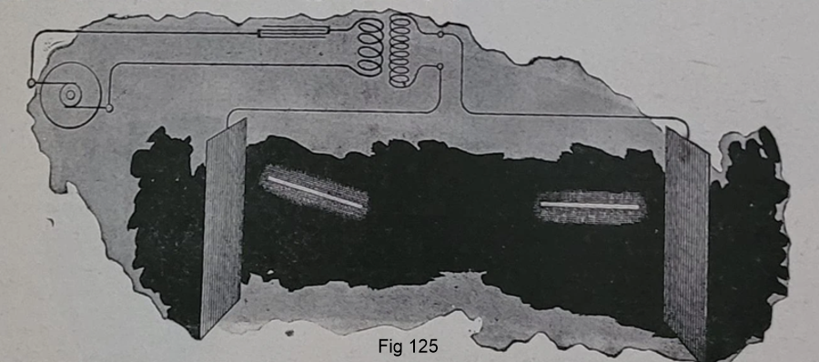
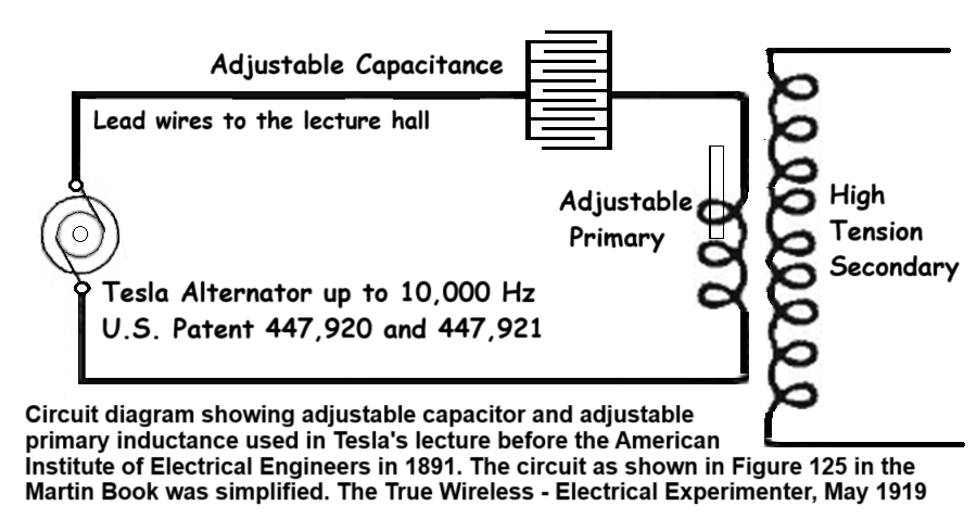
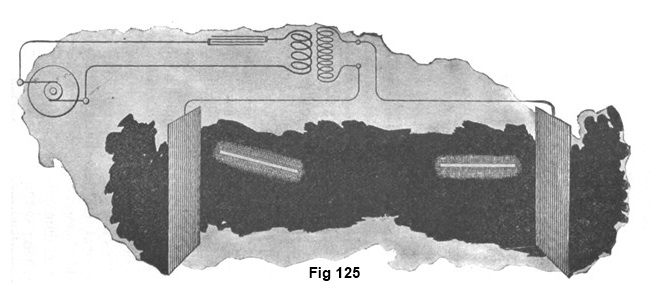
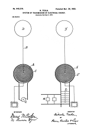
Figure 125 is the classic Tesla iron-core wireless power transmitter circuit. The circuit diagram below Figure 125 shows how the circuit was set up and tuned, with both an adjustable capacitance and adjustable primary inductance. The abreviated circuit diagrams frequently omit the capacitor, and fail to show either the capacitance or the inductance as adjustable. In practice the capacitor was always applied, and the values of both the capacitance and primary inductance were carefully adjusted to bring the circuits into tune.
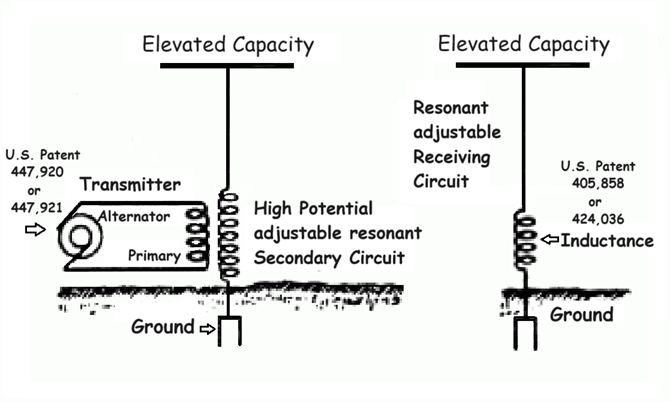
US Patents: 447,921 - 405,858 - 424,036
Figure Credit: G. Peterson, tfcbooks.com - See: Nikola Tesla on Alternating Current
The maximum power output of this machine was below 10,000 cycles per second or 10 kiloHertz, but it can produce current up to 15,000 cycles per second, or higher in some versions of the machine, with decreasing efficiency.
When used as a transmitter, as shown in the circuit development diagram above, these high-frequency alternators where directly shaft driven by powerful synchronous motors driven with isochronous generators.
Note above: the field terminals on the base that are not shown in patent.
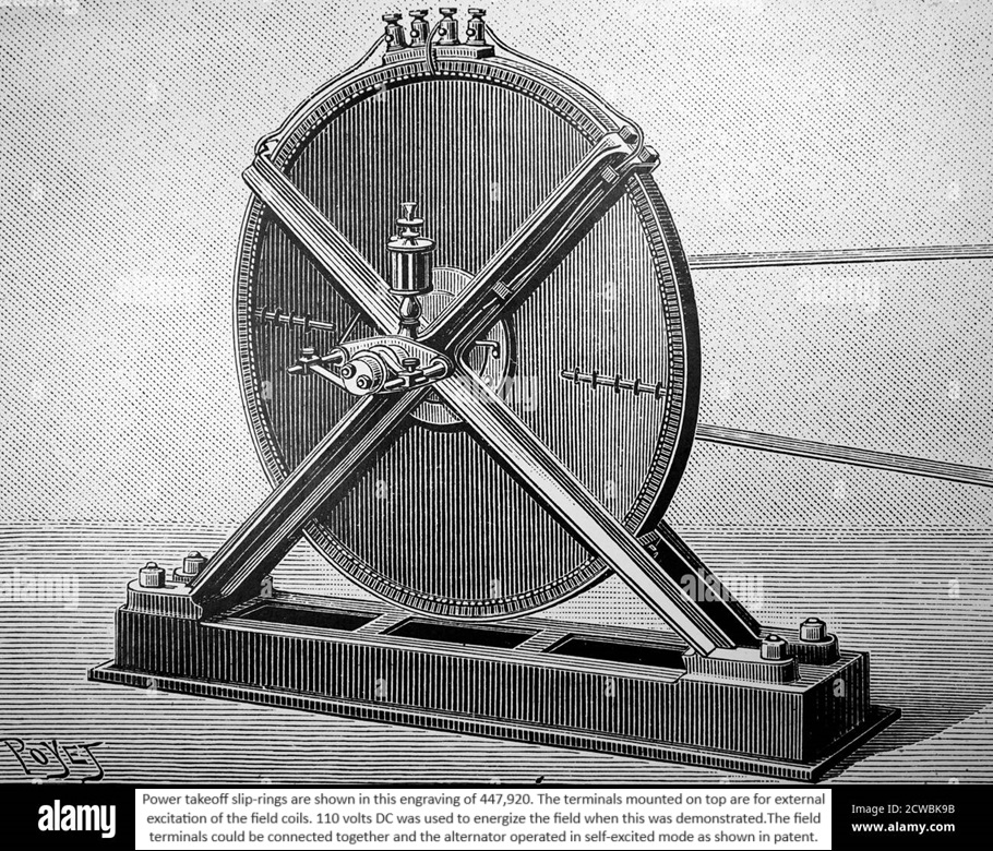
Figure 97 in the Martin Book
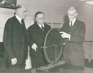
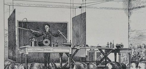
The output of the machine was sufficient, even when running at slow speed, to perform wireless energy demonstrations 18 feet across a lecture stage, as shown in Fig 125 in the Martin Book, below. The maximum output is given as 10 kilowatts in Tesla's article "The True Wireless" - Electrical Experimenter, 1919, but Tesla stated that models based on the spider type armature could produce up to 25 kilowatts.
Related Patent
447,921
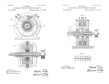
Alternating-Electric-Current Generator - Nov 15, 1890
Tesla had transmitters that worked well based on 447,920 - and - 447,921, but he was extremely limited in the power levels that could be developed with iron-shaft generators outputting between 3000 and 30,000 cycles per second. These generators had good wave forms for transmission purposes, but you could not scale them up economically without industrial support... What Tesla designed and patented was at the edge of the practical engineering limits of the time, and that is a small machine limited to about 10-25 kilowatts maximum output. If you want more output with this technology you would have to test and improve the material science and construction techniques, and then mass produce many component assemblies, like armature disks, and then synchronize them on a common shaft... It's an engineering nightmare.
By 1893 Tesla had given up development of high-frequency shaft-driven alternators for wireless transmission. He began a parallel research path into electrical oscillators, capacitive discharge power processing. The first path of development was into small desktop oscillators that operated at very low frequency, and served as working models of a global transmitter. The second development path was into the circuit controllers and the capacitors required to scale up the desktop models to a powerful high-voltage machine of many horsepower for a global transmitter.

Beginning in 1904, years after Tesla had gone with Harmonic oscillator technology, General Electric provided industrial support to electrical engineers like Ernst F. W. Alexanderson, who was influenced by the alternating current theories and mathematics of Charles Steinmetz, and whose work was actively promoted by Reginald Fessenden. Alexanderson, with General Electric industrial support, the nod by Steinmetz, and the promotion of Fessenden, developed high frequency motor driven alternators in the 50-60 kilowatt range which were used for transatlantic "long wave" wireless communications. These units took years to develop through trial and error, required material science improvements, and long hard thought into the construction techniques required. The end result were massive machines standing about 4-1/2 feet tall on the cast iron equipment mounts, about 12 feet long with the drive motor and gear box, and supported with pressurized cooling and lubrication systems. A progression of machines were built and installed at New Brunswick, NJ, and the transmitter there, operated by the U.S. Navy, broadcast reliably with up to 200 kilowatts output in 1918.
To the Archive Page Discussion on Tesla's Technology
Lab-Tesla disclosures on the technology just presented
Tesla's Cymatic Research
Steam Powered Isochronous Acoustic Oscillators & Generators
Tesla Transmitters
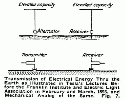
Wireless Transmission of Electrical Energy
Self-Exciting Dynamos and Alternators
Rectification, Energy Conversion
ROTATIONAL RECEPTION OF ISOCHRONOUS WAVES
Angular Displacement Receivers
EXPERIMENTS WITH ALTERNATE CURRENTS OF VERY HIGH FREQUENCY AND THEIR APPLICATION TO METHODS OF ARTIFICIAL ILLUMINATION
Lecture by N. Tesla before the American Institute of Electrical Engineers at Columbia College, N.Y., May 20, 1891
TESLA'S ALTERNATING GENERATORS FOR HIGH FREQUENCY
The Electrical Engineer, March 18, 1881; pp 338-340
The True Wireless
Electrical Experimenter, May, 1919
PHENOMENA OF ALTERNATING CURRENTS OF VERY HIGH FREQUENCY
Electrical World, Feb 21, 1891
THE TESLA EFFECTS WITH HIGH FREQUENCY AND HIGH POTENTIAL CURRENTS