Nikola Tesla's Electrical Isochronous Oscillators
Capacitive Discharge Power Processing
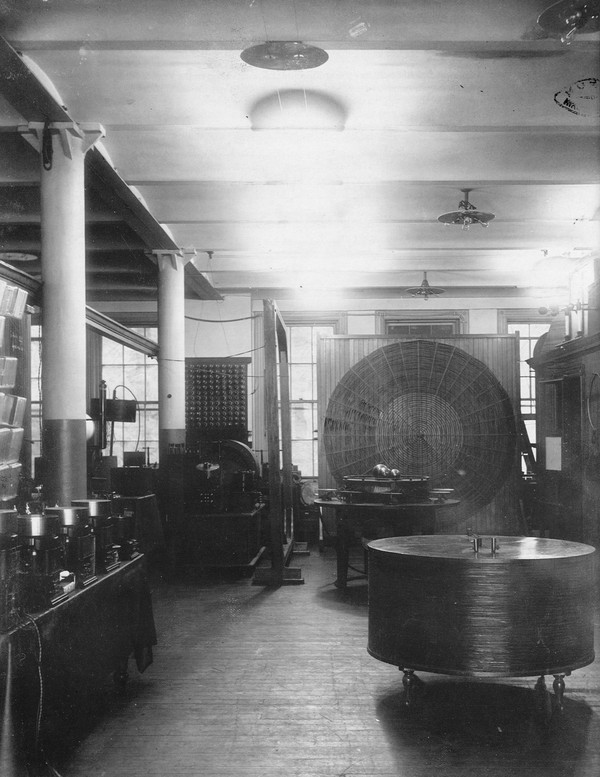
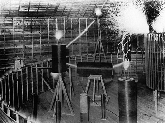
Tesla's Houston Street Laboratory Illuminated Using Patent 514,168 - Note the wireless receiver table right lower front.
On the table left are a row of compact electrical isochronous oscillators with liquid mercury rotary switches
or "circuit controllers" on top.
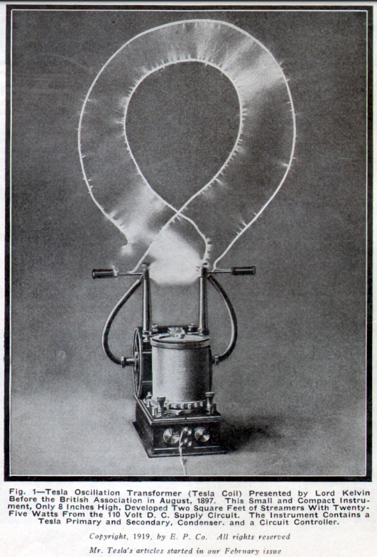
See Tesla's article in: Electrical Experimenter, July 1919
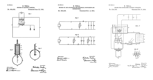
454,622
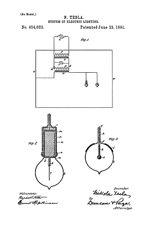
System of Electric Lighting - Apr 25, 1891
462,418
Method of and Apparatus for Electrical Conversion and Distribution - Feb 4, 1891
514,168
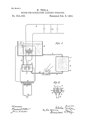
Means of Generating Electric Currents - Aug 2 1893
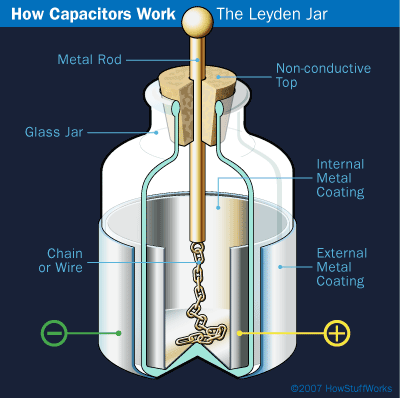
Tesla used Leyden jars in his first lectures (depicted on the table), in his exhibits (two groups of jars on the left side table), and in the laboratory. His first oscillators used Leyden jars. Tesla gradually replaced the jars with oil capacitors, salt water capacitors, and large mica plate capacitors (detailed below).
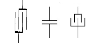
Circuit diagram symbols Tesla uses for capacitance.
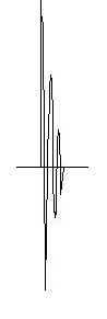
Above is a chart showing the voltages over time of the discharge of a capacitor oscillating through a coil. The frequency of these oscillations is dependant on the capacitor and coil sizes. The resistance, losses to radiation, and dielectric losses in the capacitor mean each oscillation cycle contains less energy and therefore a lower voltage until the capacitor discharges completely. These are called "damped oscillatory waves".
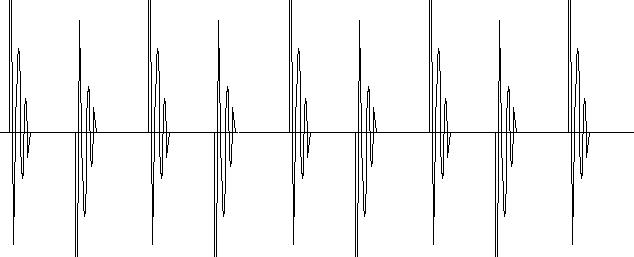
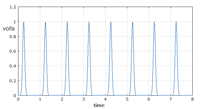
Above is a chart showing a train of capacitor discharge oscillations, with regular time intervals to recharge the capacitor. The time interval between discharges is determined by the switch.
It had been known since Henrich Hertz that charging a capacitor, they used Leyden jars in those days, with a high-voltage static machine, then discharging the capacitor through a short coil produced oscillations. It was discovered through measurements that these oscillations were perfectly timed, and that the frequency of these oscillations were dependent on the size of the jar (capacitor), and the size of the coil. A large coil, discharging a large jar, or a bank of jars connected together in parallel, produced a lower frequency... But even these "lower frequencies" are very high compared to the operating frequencies of Tesla iron core generators, and iron shaft reciprocating oscillators. The normal operation of all of these circuits is to produce pulses at an audio frequency rate, but usually the pulses themselves are very high-frequency oscillations (exceptions below). These high-frequency oscillations are produced by energy bouncing back and forth from one capacitor plate to the other, like a spring. These high-frequency oscillations are maintained with a declining amplitude until the electrical fire, or arc, that forms in the spark gap is broken, or "quenched".
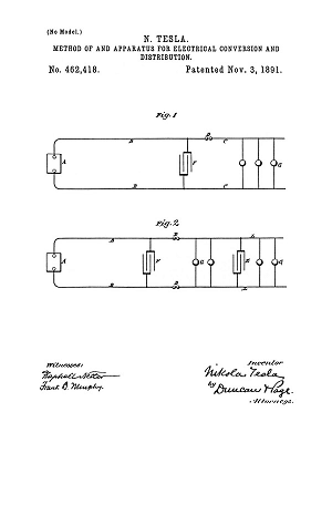
U.S. Patent 462,418
Tesla wholly embraced the concept of capacitive discharge. He developed the Hertz oscillator into a continuosly operating, pulse power output circuit.
A simple spark gap for a neon sign transformer powered Tesla coil.
Image courtesy of: The Fragmentation Paradox
First Tesla Oscillator - U.S. Patent 462,418
The Classic Tesla Coil - U.S. Patent 454,622
The first circuits were switched with simple air gaps, a technology that was very familiar to The Arc-Light Men.
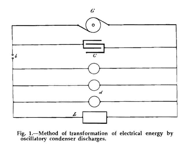
These circuits were patented (above and below) and they were repeatedly demonstrated in lectures below. In Fig. 1 above, patented in 462,418, G represents an alternating current power supply. The circuit diagram above shows a generator, and a specially constructed generator can be used here, but in practice this symbol actually represents an entire power supply: a generator and a voltage step-up transformer are typically used as the capacitor must charge to a high enough voltage for a spark to jump the air gap b and trigger the oscillation of current between the capacitor plates C and lamps d and motor L. Tesla assigns different lettering here and there, usually lamps are labled small case "l" and motors are small case "m", spark gaps are small case "d", but the circuit diagram symbols always represent the same ideas. DC power supplies are sometimes diagrammed as rectangular boxes, representing a large high-voltage battery, but later patent diagrams have DC power specified in the text where it is applied. Tesla sometimes refers to "municipal current", and this specifically refers to 110 volt DC power that was available at the time in some municipalities and nearly every large institution.
The above chart shows a non-oscillatory pulse train of the type produced by 462,418 - Fig 2 - with careful adjustment. These waveforms were researched and developed for the purpose of exciting harmonic oscillators, - motor fields, - and for pulse ground wave transmitters. But as mentioned previously, all the other circuits here are designed to oscillate, and 462,418 oscillates by default. You have to set it up carefully to get the wave train in the above figure, the air gaps have to be carefully quenched, but it can be done.
EXPERIMENTS WITH ALTERNATE CURRENTS OF HIGH POTENTIAL AND HIGH FREQUENCY
ON LIGHT AND OTHER HIGH FREQUENCY PHENOMENA
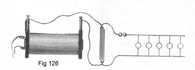
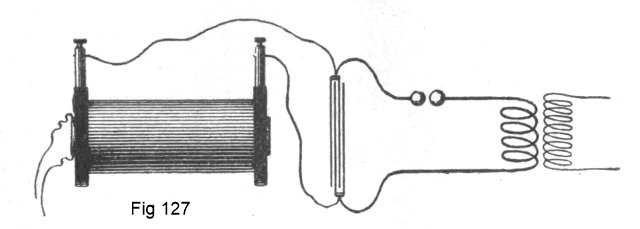
Above: Early European Tesla Coil that was made following Tesla's lectures overseas. T is an ordinary induction coil with a single layer secondary on a wooden spool, with the primary inside. It is submerged in a glass tank full of clear mineral oil. - L is the Leyden jar, "e" is the primary or "tank circuit" spark gap and E are the output terminals with high frequency Tesla energy. Not shown is a low frequency conventional type high voltage induction coil used to charge the Leyden jar.
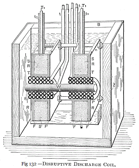
In 1892 Tesla demonstrated a coil designed and constructed to be submerged in oil. In US Patent 514,168 - Tesla resorts to placing the entire circuit, capacitor, and the rotary switch, under oil. The importance of excluding all gas from the windings of high-frequency equipment was discussed by Martin as well as Tesla.
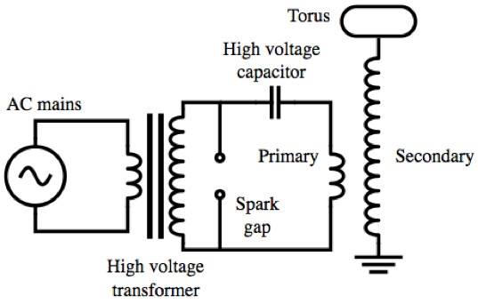
The classic spark gap Tesla Coil is directly descended from these patents and lecture demonstrations. These circuits as shown are designed to process power. The capacitor in the circuit accepts a high-voltage charge over a period of time. When the charge is developed, it is discharged with a switch into a short heavy coil. It takes a period of time to charge a capacitor, but the discharge is very, very rapid. Because of the rapid rate of discharge, the peak energy delivered by a capacitor can be very, very large. The oscillator performance depends on the circuit design and quality, especially the capacitor quality, and the switch.
The first switches were simple voltage triggered air gaps: when the capacitor charged, the voltage rose: the air gap was adjusted to discharge when the capacitor voltage was at or near its peak. These work pretty well for discharging the capacitor, but the switch does not want to turn off easily. Tesla immediately began developing the technology with a goal of being able to produce clean sine waves, -- "damped oscillatory" waves - and - isochronous pulse wave trains. He worked extensively on improving the switching performance. Rotary switching was introduced in lecture in 1893, and extensive patent documentation of high-precision rotary switching technology was recorded.

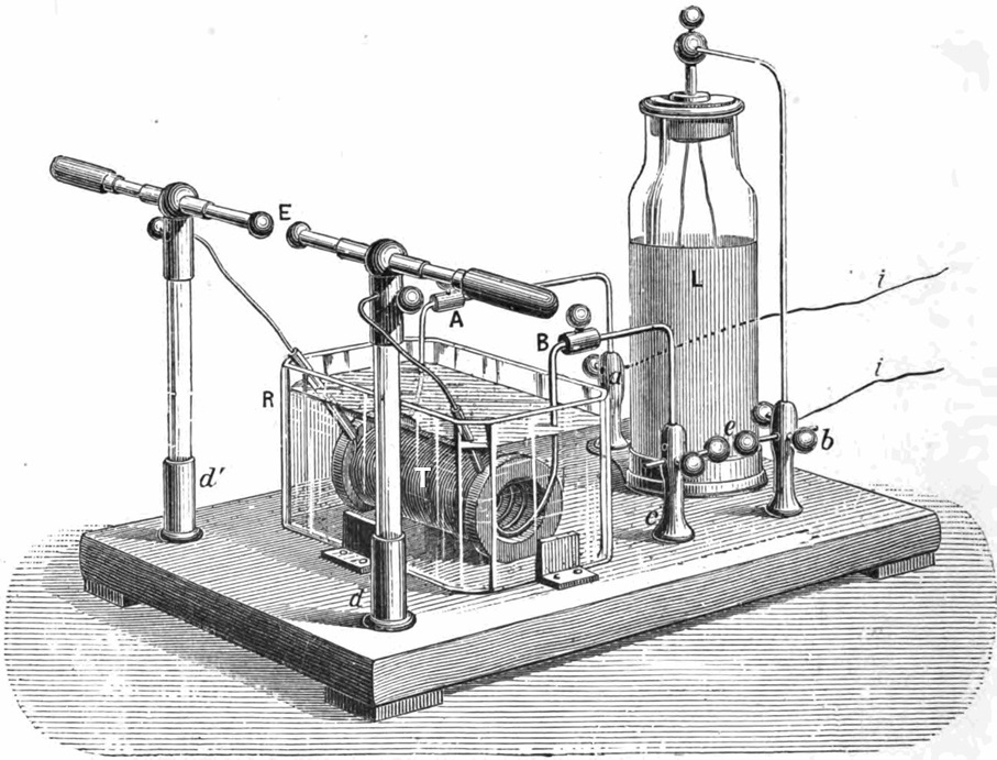
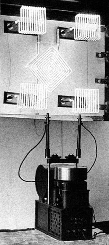
"This [Fig above] is the apparatus I had at 35 South Fifth Avenue and also Houston Street. It shows the whole arrangement as I had it for the demonstration of effects which I investigated. This cable you see [square loop in top half of the Fig above] is stretched around the hall. These are my condensers. There is the mechanically operated break, and that is a transformer charged from the generator. That is the way I had it for the production of current effects which were rather of damped character because, at that period, I used circuits of great activity which radiated rapidly. In the Houston Street laboratory, I could take in my hands a coil tuned to my body and collect 3/4 horsepower anywhere in the room without tangible connection, and I have often disillusioned my visitors in regard to such wonderful effects. Sometimes, I would produce flames shooting out from my head and run a motor in my hands, or light six or eight lamps. They could not understand these manifestations of energy and thought that it was a genuine transmission of power. I told them that these phenomena were wonderful, but that a system of transmission, based on the same principle, was absolutely worthless. It was a transmission by electromagnetic waves. The solution lay in a different direction. I am showing you this [diagram] simply as a typical form of apparatus of that period, and if you go over the literature of the present day you will find that the newest arrangements have nothing better to show."
Nikola Tesla - New York, 1919
This was just one of many, many oscillator circuits Tesla used in the New York labs, but it was the most powerful. The square conductor at the top of the image was a loop of cable run around the ceiling molding. The diagram inside the circuit is the rotary switch design Tesla used to switch the capacitors from charging to discharge mode. Typically in this arrangement the rotary switch was directly driven from the generator shaft. This inductive transmitter circuit was first patented as a System of Electrical Lighting in 454,622, and was disclosed in Tesla's lecture before the American Institute of Electrical Engineers in Fig 127, but the power levels are rising, the switch performance is improving, and the data obtained leads directly to the drive circuits for the Colorado Springs and Wardenclyffe oscillators. The inductive receivers Tesla developed were photographed in both the NY and Wardenclyffe laboratories.
- As Tesla states, the above circuit, and others like it, are really not suitable for commerical wireless power transmitters. But it was patented as an inductive transmitter and source for the control signal in U.S. Patent 613,809, among other transmitter techniques he included.
Increasing the switch rates combined with the energy developed by discharging larger, higher-voltage, capacitors produces harmonic responses in closely inductively coupled secondary coils in these oscillators. Tesla discovered that when the secondary coils on high-frequency transformers are over-driven with capacitive discharge oscillators, the fundamental frequency of operation in the secondary coil splits into a Harmonic Series. This is very predictable, both mathematically and practically. Tesla realized that an entire spectrum of these harmonics are continuous sine waves if the circuits are set up and operated correctly. Furthermore these continuous sine waves can be selectively modulated at the transmitter.
Tesla was a close friend of Professor Elisha Gray. A great deal of Gray's work, nearly all of it in fact, was intended to be applied to Tesla's wireless system.
Receiving Table for Tesla Wireless, used in the above oscillator system.

Tesla's Capacitor Development
As part of the development of his electrical oscillator technology, Tesla filed patents covering the improvement of capacitors (condensers) using mineral oil, a new type of capacitor with liquid electrolyte (salt water) plates, and a new method of manufacturing capacitors, coils, etc..
464,667
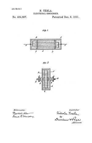
Electrical Condenser - Aug 1, 1891
567,818
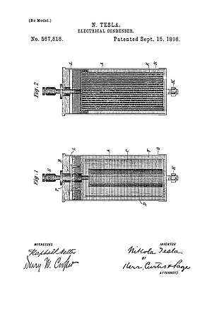
Electrical Condenser - Jan 2, 1892
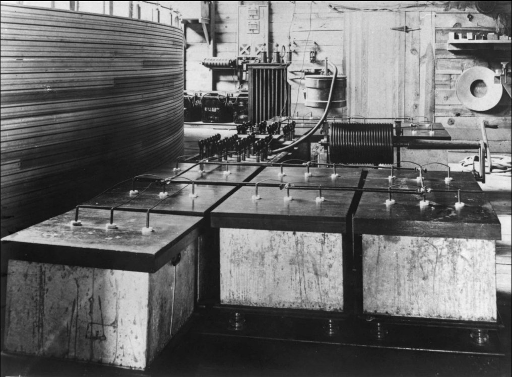
In this photo above (click image for higher resolution) of Tesla's Colorado Springs oscillator the square tanks in the foreground, mounted on insulated platforms, are large liquid electrolyte (salt water) capacitors covered under the patent above. The tanks are made from tin which was soldered up make them water tight, they form one plate of the salt water capacitor and an electrical connection was made to the tin. Inside the tank were mineral water bottles with copper terminals dropped inside and filled 2/3rds with salt water. The glass in the bottles formed the capacitor dielectric, the insulator, just like a Leyden jar. The tank was filled with salt water to a height equal to the fluid level in the bottles. The necks of the bottles, above the salt water level, were carefully cleaned and dried and then the whole works was covered in oil to insulate the glass bottle necks, suppress corona, and prevent flashovers. The carefully insulated leads from each bottle were connected together into one of three buses and brought out through three holes in the oiled wooden non-conductive covers that went over the tanks. Bottles frequently broke down under the electrical stress, the covers were removed, and the broken bottles were replaced as required. Tesla tested all of the various types of glass bottles available in sufficient quantity to complete the project, finding a brand with superior quality glass for building a large oscillator.
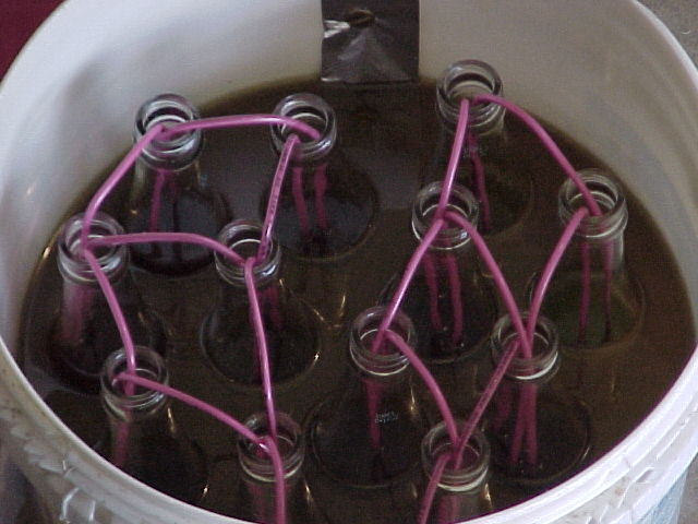
Above: Modern homemade salt water capacitor. Many people still use glass bottles for homemade Tesla coil capacitors, but I knew a guy that ran 10 kilowatt coils with a couple of stacks of Home Depot buckets with salt water in between buckets for the plates. When the buckets were pressed together the salt water was forced up into the space between the sides of the buckets, greatly increasing the capacitance, and they never failed. They were simple, cheap, rugged, and he sealed the buckets together with silicone once he got the fluid levels correctly set. Once sealed they didn't leak. Each joint between buckets had a strip of aluminum inserted from a can that had been sanded bare. One end of the aluminum strip made contact with the brine, the middle was sealed in with silicone, and the end that stuck out had a hole in it for a nut and bolt connection to a wiring harness with ring terminals. Ten or twelve Home Depot buckets and he needed a utility distribution transformer to charge them. Modern plastic film capacitors work well when connected together into arrays, but nothing beats salt water for large very inexpensive capacitance.
577,671
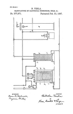
Manufacture of Electrical Condensers, Coils, & Etc. - Nov 5, 1896
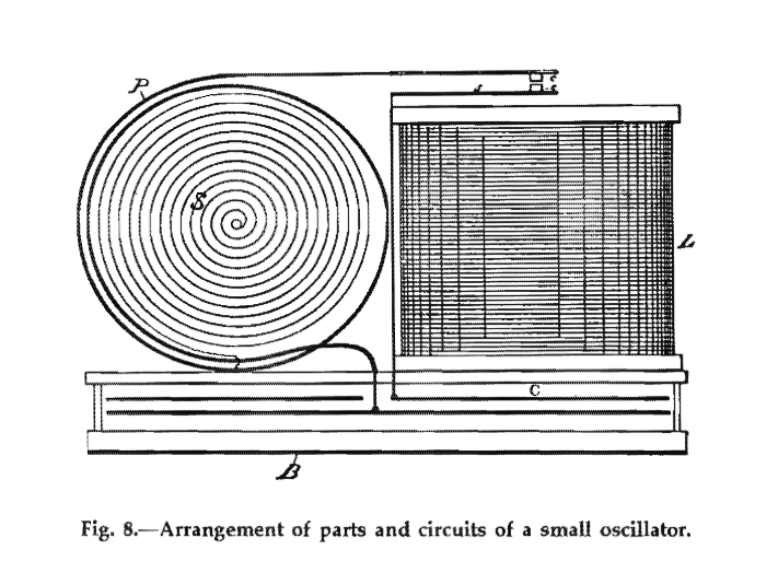
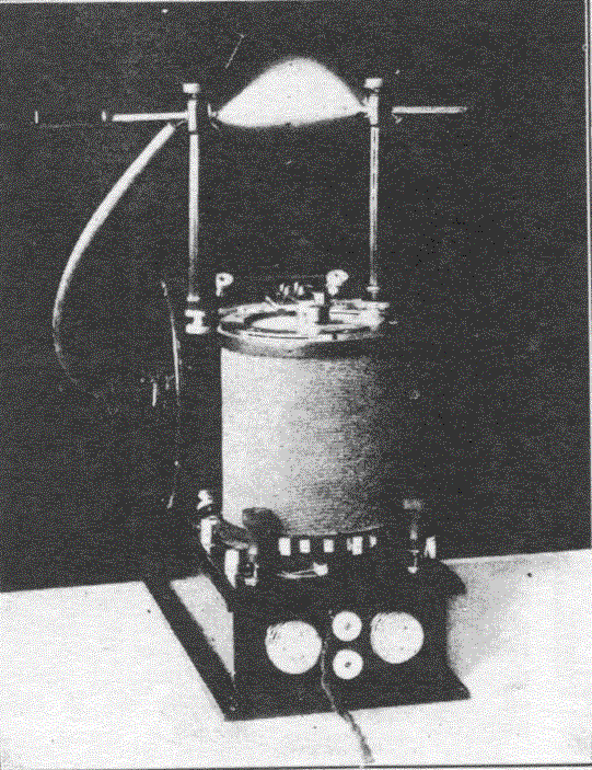
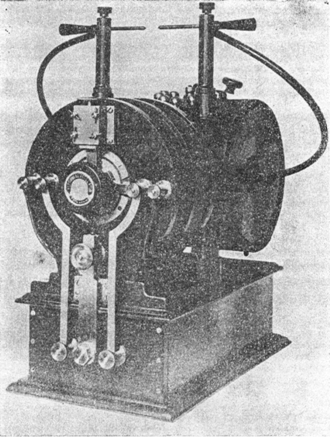
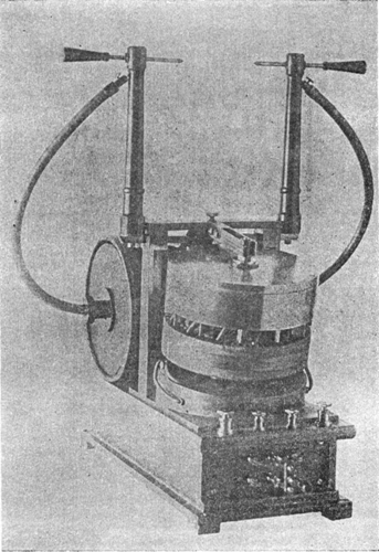
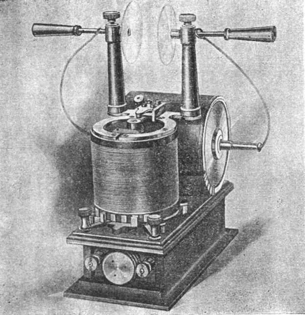
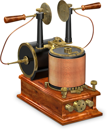
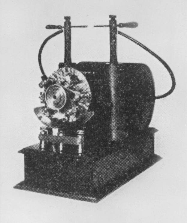
The equipment in the photographs below was all constructed using the technique patented in 577,671 for the manufacture of the capacitors and coils. The wooden base cabinet contains one or more high-quality mica plate capacitors which were encapsulated in high-temperature sealing wax applied under hydraulic pressure, after hard vacuum pumping. The capacitor terminals come through the wooden boxes to make connections to the charging circuit, switch, and primary coil. A magnetic vibrating contact point is shown in Fig. 8 above, rotary switches were later used.
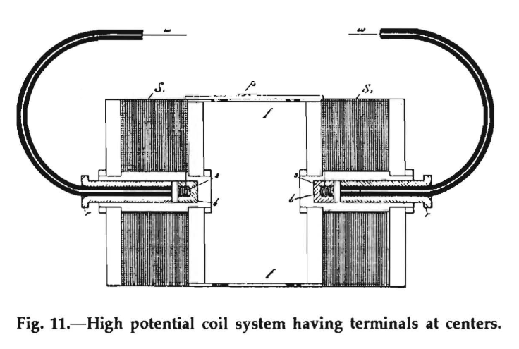
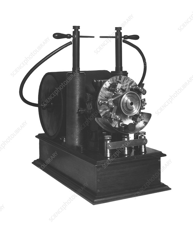
Photos of equipment are not matched up to specific patents.
568,176
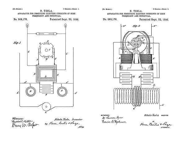
Apparatus for Producing Electrical Currents of High Frequency and Potential - April 22, 1896
568,177
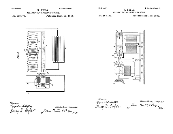
Apparatus for Producing Ozone - June 17, 1896
568,178
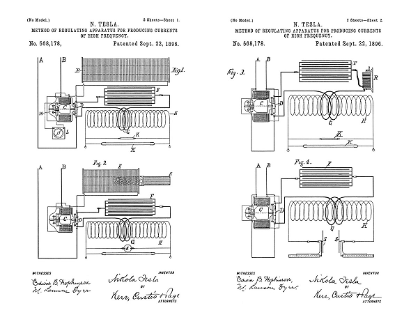
Method of Regulating Apparatus for Producing Currents of High Frequency - June 20, 1896
568,179
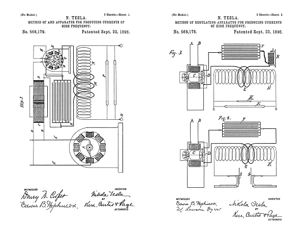
Method of and Apparatus for Producing Currents of High Frequency - July 6, 1896
568,180
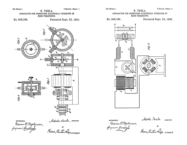
Apparatus for Producing Electrical Currents of High Frequency - July 9, 1896
577,670
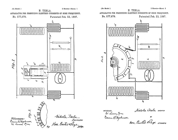
Apparatus for Producing Electrical Currents of High Frequency - Sept 3, 1896
583,953
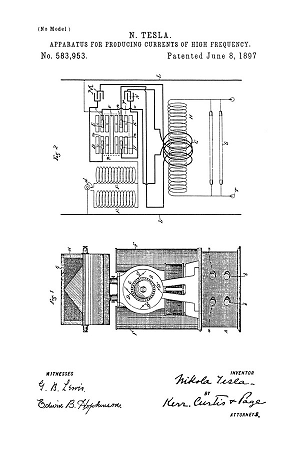
Apparatus for Producing Currents of High Frequency - Oct 19, 1896
By 1893 in the development record Tesla had given up further work on high-energy, high-frequency, alternators based on 447,920 and 447,921 for wireless transmitters. He had shifted over to resonant electrical oscillator circuits to replace the high frequency alternators. Many of these oscillators above operated at extremely low frequencies and were capable of coupling to, and rotating, high frequency motor armatures. The mica plate capacitor values were very large, but they were not rated for high-voltage, and the circuit controllers all used positive electrical contacts: the operating voltages on the capacitors were not large enough to jump a spark gap. However using the large capacitor value, precision switching, and large secondary coils wound from great lengths of very fine wire: Tesla was able to desktop model a low power transmitter geometry suitable for practical scaling to a global transmitter. It was these oscillators that directly lead to the final transmitter patent: 1,119,732
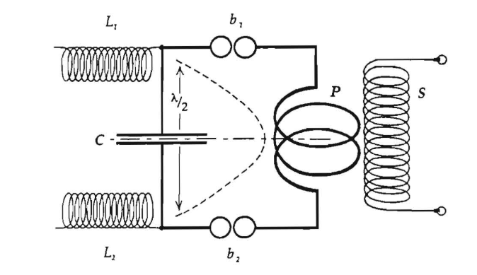
System of concatenated tuned circuits shown and described in Tesla U.S. Patent No. 568,178 of September 22, 1896, and corresponding arrangements in wireless transmission.
The True Wireless, Electrical Experimenter, May, 1919.
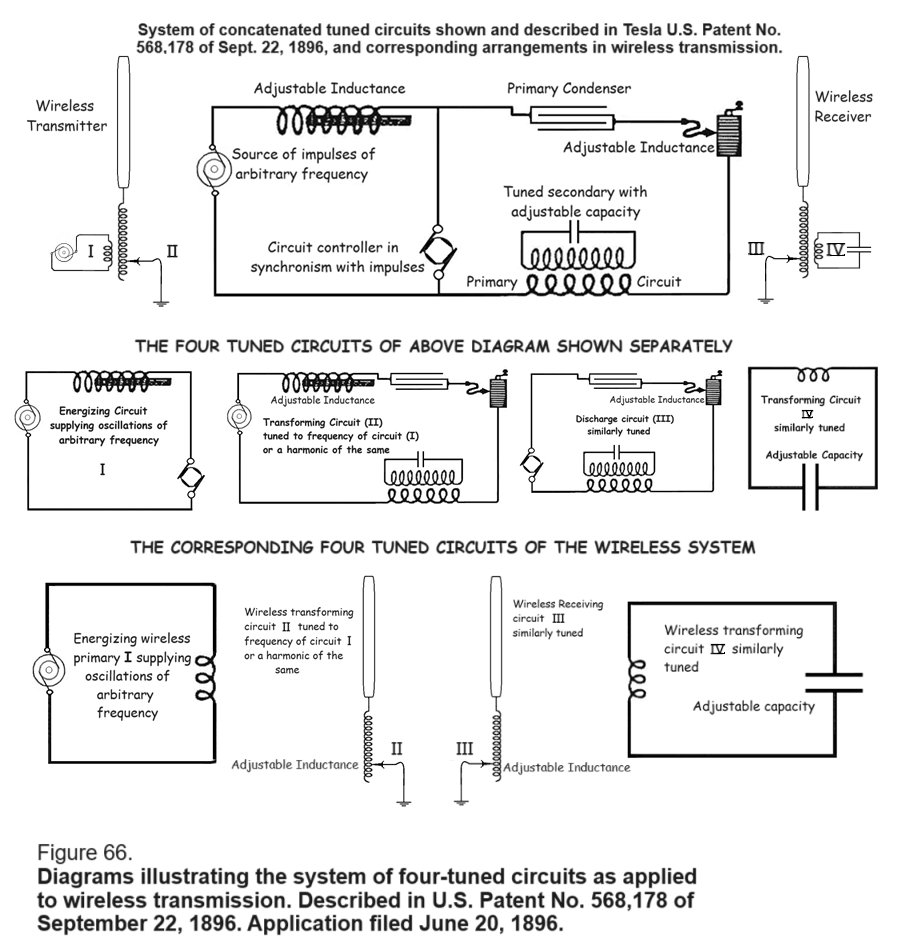
See: Nikola Tesla on Alternating Current, Figure 66.
Electrical Oscillators
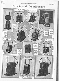
Electrical Experimenter, July, 1919
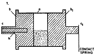
Tesla's Electric Circuit Controllers
Precision Switching Technology
Tesla's Cymatic Research
Steam Powered Isochronous Acoustic Oscillators & Generators
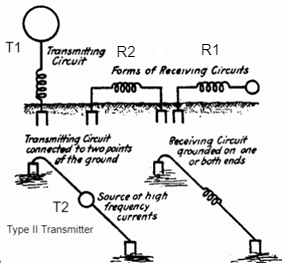
Tesla Transmitters
Wireless Transmission of Electrical Energy
Tesla's Oil Submersion Technology

Corona and arc suppression using liquid insulators
Tesla's Coherer Technology
Wireless Communications Receivers
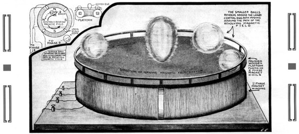
Tesla's Egg of Columbus
Electrical Experimenter, March, 1919
Tesla's Laboratory Power
Boiler, Steam Engine, Line-Shaft, Belts & Pulleys
Nikola Tesla Receiver Technology
Home Appliances and Industrial Solutions
To the Archive Page Discussion on Tesla's Technology
Lab-Tesla disclosures on the technology just presented
Some people find us because they want to construct Tesla Coils for the purposes of producing artificial lightning.
High Performance Tesla Resonator Design
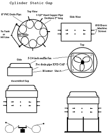
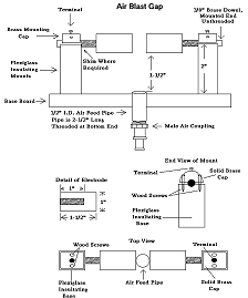
High Performance Air-Blast Spark Gap