The Electrical Engineer, March 18, 1891, pp 338-340
TESLA'S ALTERNATING GENERATORS FOR HIGH FREQUENCY
[See: US Patent 447,920 and US Patent 447,921]
It has now become a common practice to run arc lamps by alternating or pulsating, as distingushed from continous, currents; but an objection which has been raised to such systems exists in the fact that the arcs emit a pronounced sound, varying with the rate of the alternations or pulsations of current, for which, up to present, no effective remedy has been found. This noise is due to the rapidly alternating heating and cooling, and consequent expansion and contraction, of gaseous matter forming the arc which corresponds to the periods or impulses of the current. Another disadvantageous feature is found in the difficulty of maintaining an alternating current arc in consequence of the periodical increase in resistance corresponding to the periodical working of the current. This feature entails further disadvantgees, namely, that small arcs are impractical.
Theorectical considerations have led Mr. Tesla to the belief that these disadvantageous features could be obviated by employing currents of sufficiently high number of alternations and his anticipations have been confirmed in practice. These rapidly alternating currents render it possible to maintain small arcs which, besides, possess the advantages of silence and persistency. The latter quality is due to the necessarily rapid alternations, in consequence of which the arc has no time to cool, and is always maintained at a high temperature and low resistance
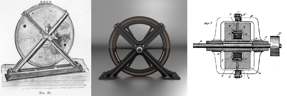
At the outset of his experiments Mr. Tesla encountered great difficulties in the construction of these machines. A generator of this kind is described here, which, though constructed quite some time ago, is well worthy of a detailed description.
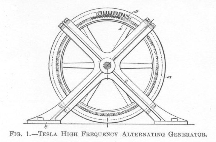
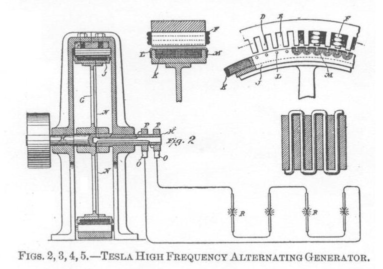
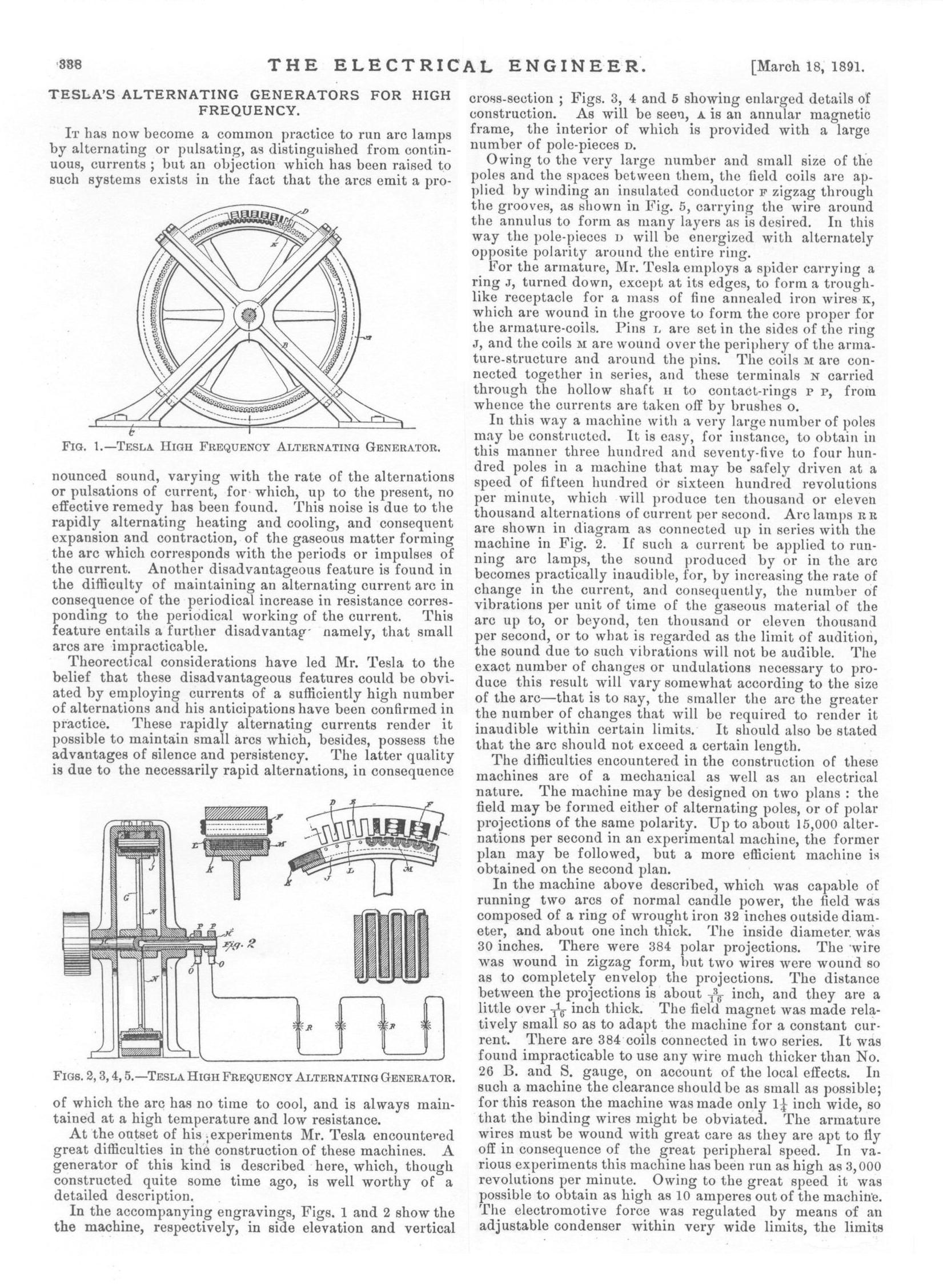
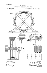
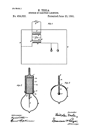
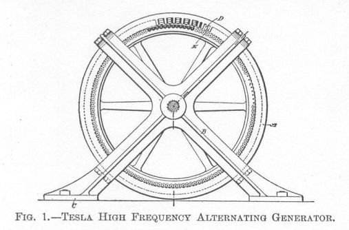
In the accompanying engravings, Figs 1 and 2 show the machine, respectively, in side elevation and vertical cross-section ; Figs 3, 4, and 5 showing enlarged details of construction. As will be seen, A is an annular magnetic frame, the interior of which is provided with a large number of pole-pieced D.
Owing to the very large number and small size of the poles and the spaces between them, the field coils are applied by winding an insulated conductor F zigzag through the grooves, as showing in Fig. 5, carrying the wire around the annulus to form as many layers as desired. In this way the pole-pieces D will be energized with alternately opposite polarity around the entire ring.
For the armature, Mr. Tesla employs a spider carrying a ring J, turned down, except at its edges, to form a trough-like receptacle for a mass of fine annealed iron wires K, which are wound in the groove to form the core proper for the armature-coils. Pins L are set in the sides of the ring J, and the coils M are wound over the periphery of the aramature-structure and around the pins. The coils M are connected together in series, and these terminals N carried through the hollow shaft H to contact-rings P P, from whence the currents are taken off by brushes O.
In this way a machine with a very large number of poles may be constructed. It is easy, for instance, to obtain in this manner three hundred and seventy-five to four hundred poles in a machine that may be safely driven at a speed of fifteen hundred or sixteen hundred revolutions per minute, whic will produce ten thousand or eleven thousand alternations of current per second. Arc lamps R R are shown in diagram as connected up in series with the machine in Fig. 2. If such a current be applied to running arc lamps, the sound produced by or in the arc becomes practically inaudible, for, by increasing the rate of change in the current, and consequently, the number of vibrations per unit of time of gaseous material of the arc up to, or beyond, ten thousand or eleven per second, or to what is regarded as the limit of audition, the sound due to such vibrations will not be audible. The exact number of changes or undulations necessary to produce this result will vary somewhat according to the size of the arc - that is to say, the smaller the arc the greater the number of changes that will be required to render it inaudible within certain limits. It should also be stated that the arc should not exceed a certain length.
The difficulties encountered in the construction of these machines are of mechanical as well as an electrical nature. The machine may be designed on two plans: the field may be formed either of alternating poles, or of polar projections of the same polarity. Up to about 15,000 alternations per second in an experimental machine, the former plan may be followed, but a more efficient machine is obtained on the second plan.
In the machine above described, which was capable of running two arcs of normal candle power, the field was composed of a ring of wrought iron 32 inches outside diameter, and about one inch thick. The inside diameter was 30 inches. There were 384 polar projections. The wire was wound in a zigzag form, but two wires were wound so as to completely envelop the projections. The distance between the projections is about 3⁄16 inch, and they are a little over 1⁄16 thick. The field magnet was made relatively small so as to adapt the machine for constant current. There are 384 coils connected in two series. It was found impracticable to use any wire thicker than No. 26 B. and S. gauge, on account of the local effects. In such a machine the clearance should be as small as possible; for this reason the machine was made only 11⁄4 inch wide, so that the binding wires might be obviated. The armature wires must be wound with great care as they are apt to fly off in consequence of the great peripheral speed. In various experiments this machine has been run as high as 3,000 revolutions per minute. Owing to the great speed it was possible to obtain as high as 10 amperes out of the machine. The electromotive force was regulated by means of an adjustable condenser within very wide limits, the limits being the greater, the greater, the greater the speed. This machine was frequently used to run Mr. Tesla's shop lights.
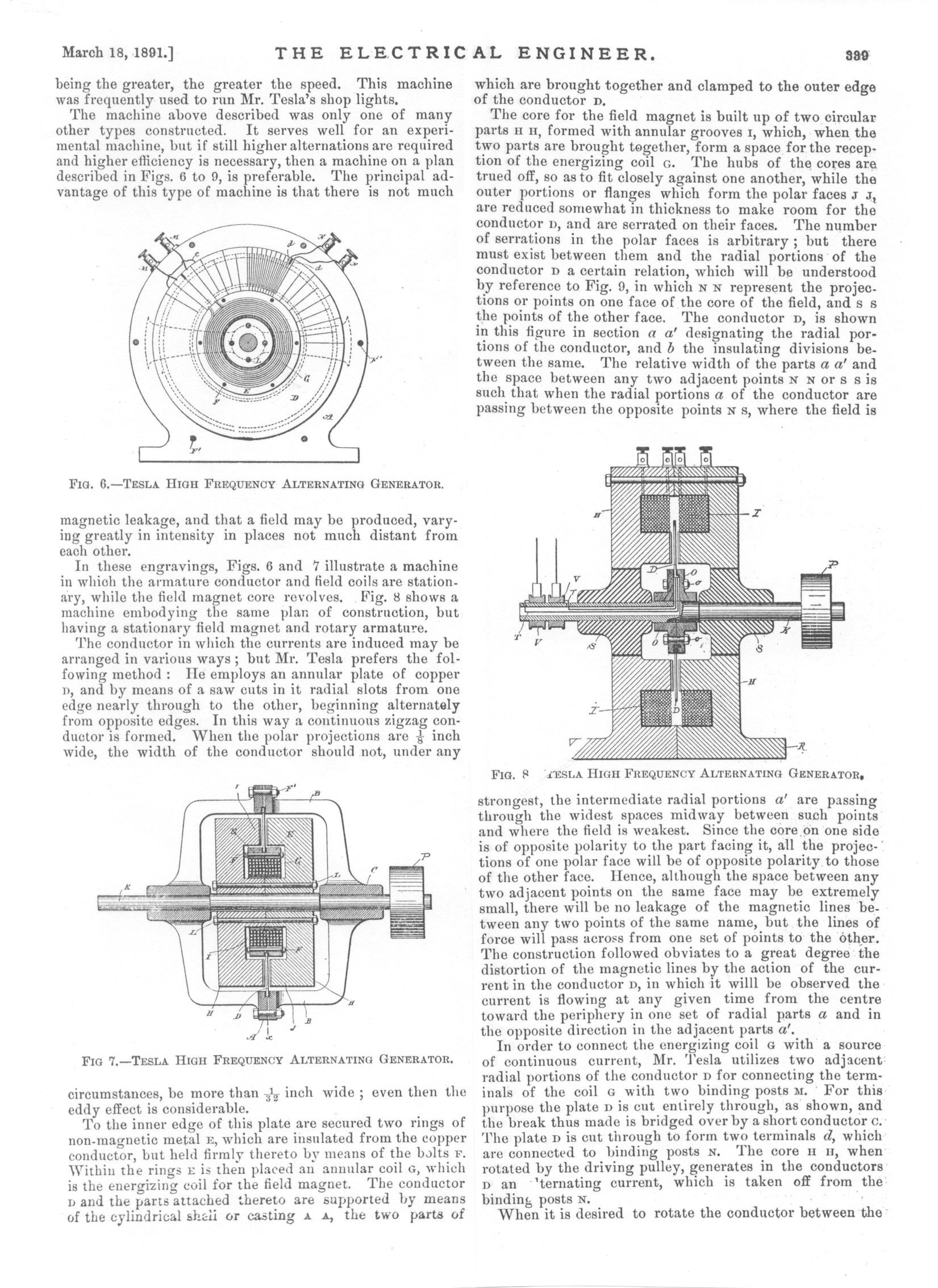
The machine above described was only one of many other types constructed. It serves well for an experimental machine, but of still higher alternations are required and higher efficiency is necessary, then a machine on a plan described in Figs. 6 to 9, is preferable. The principal advantage of this type machine is that there is not much magnetic leakage, and that a field may be produced, varying greatly in intensity in places not much distant from each other.
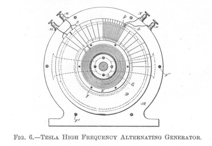
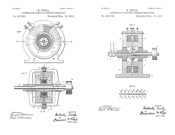
In these engravings, Figs. 6 and 7 illustrate a machine in which the armature conductor and field coils are stationary, while the field magnet core revolves. Fig. 8 shows a machine embodying the same plan of construction, but having a stationary field magnet and rotary armature.
The conductor in which the currents are induced may be arranged in various ways; but Mr. Tesla prefers the following method: He employs an annular plate of copper D, and by means of a saw cuts in it radial slots from one edge nearly through to the other, beginning alternately from opposite edges. In this way a continous zigzag conductor is formed. When the polar projections are 1⁄8 inch wide, the width of the conductor should not under any circumstances, be more than 1⁄32 inch wide ; even then the eddy effect is considerable.
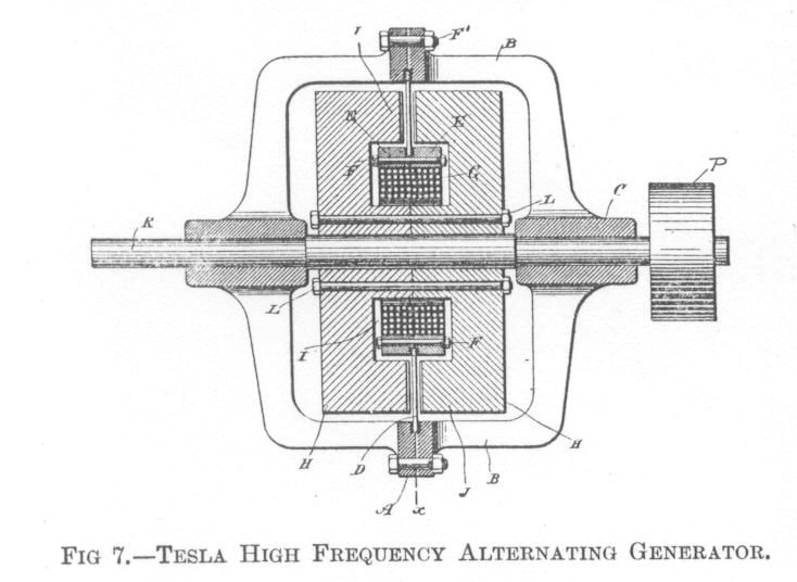
To the inner edge of this plate are secured two rings of non-magnetic metal E, which are insulated from the copper conductor, but held firmly thereto by means of bolts F. Within the rings E is then placed an annular coil G, which is the energizing coil for the field magnet. The conductor D and the parts attached thereto are supported by means of the cylindrical shell or casting A A, the two parts of which are brought together and clamped to he outer edge of the conductor D.
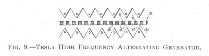
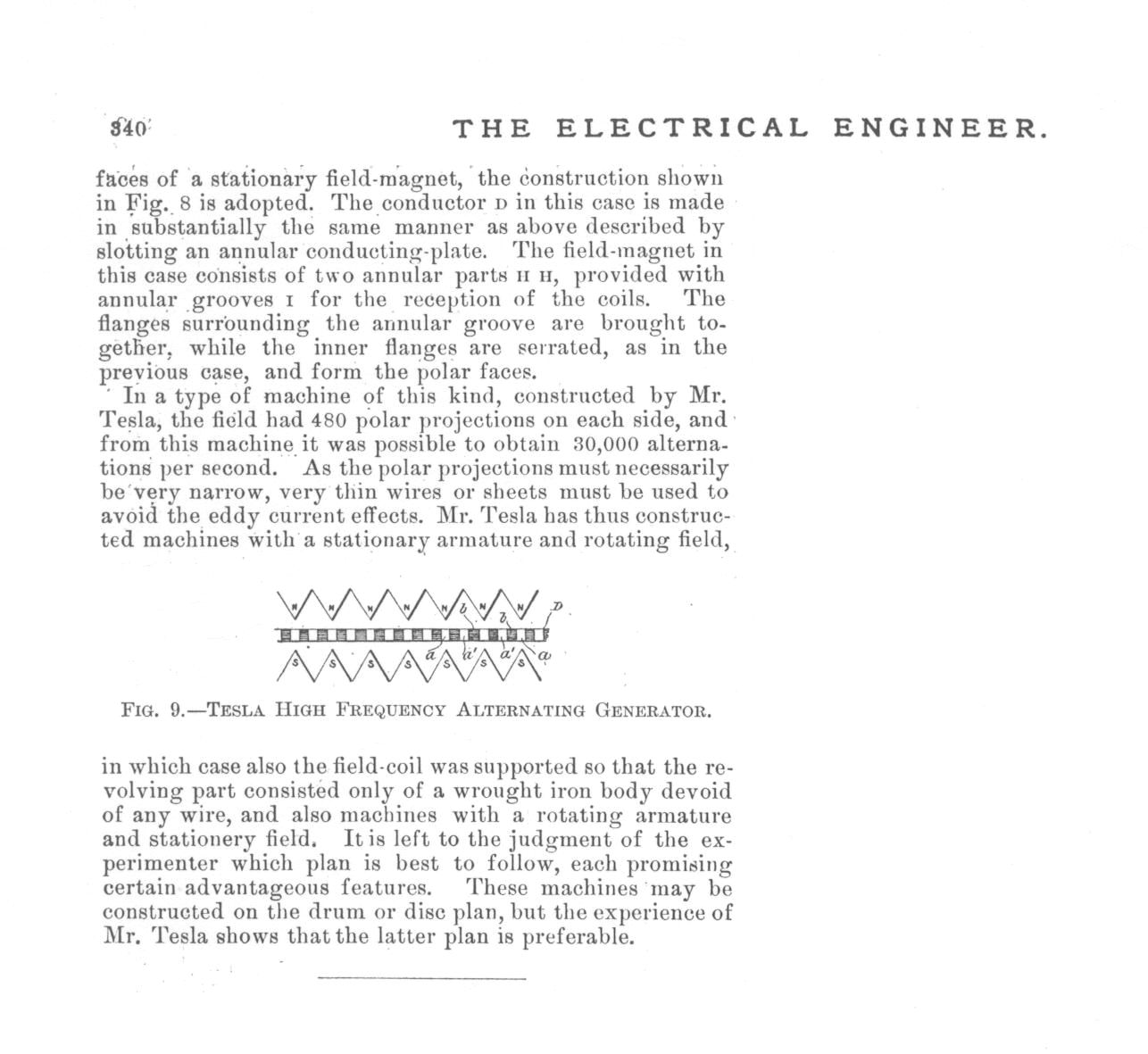
The core for the field magnet is built up of two circular parts H H, formed with annular grooves I, which, when the two parts are brought together, form a space for the reception of the energizing coil G. The hubs of the cores are trued off, so as to fit as closely against one another, while the outer portions or flanges which form the polar faces J J, are reduced somewhat in thickness to make room for the conductor D, and are serrated on their faces. The number of serrations in the polar faces is arbitrary; but there must exist between them and the radial portions of the conductor D a certain relation, which will be understood by reference to Fig. 9, in which N N represent the projections or points on one face of the core of the field, and S S the points of the other face. The conductor D, is shown in this figure in section a a' designating the radial portions of the conductor, and b the insulating divisions between the same. The relative width of the parts a a' and the space between any two adjacent points N N or S S is such that when the radial portions a of the conductor are passing between the opposite points N S, where the field is strongest, the intermediate radial portions a' are passing through the widest spaces midway between such points and where the field is weakest. Since the core on one side is of opposite polarity to the part facing it, all the projections of one polar face will be of opposite polarity to those of the other face. Hence, although the space between any two adjacent points on the same face may be extremely small, there will be no leakage of the magnetic lines between any two points of the same name, but the lines of force will pass across from one set of points to the other. The construction followed obviates to a great degree the distortion of the magnetic lines by the action of the current in the conductor D, in which it will be observed the current is flowing at any given time from the center toward the periphery in one set of radial parts a and in the opposite direction in the adjacent parts a'
In order to connect the energizing coil G with a source of continuous current, Mr. Tesla utilizes two adjacent radial portions of the conductor D for connecting the terminals of the coil G with the two binding posts M. For this purpose the plate D is cut entirely through, as shown, and the break thus made is bridged over by a short conductor C. The plate D is cut through to form two terminals d, which are connected to binding posts N. The core H H, when rotated by the driving pulley, generates in the conductors D an alternating current, which is taken off from the binding posts N.
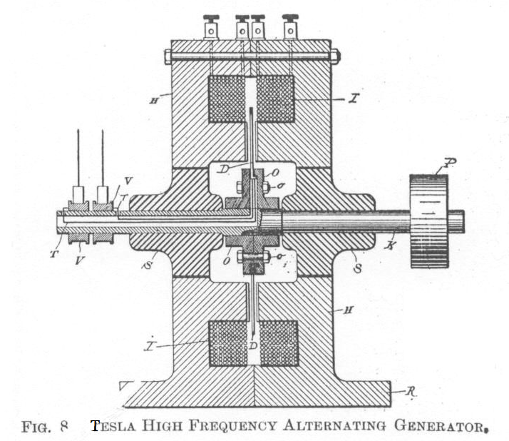
When it is desired to rotate the conductor between the faces of a stationary field-magnet, the construction shown in Fig. 8 is adopted. The conductor D in this case is made in substantially the same manner as the above described by slotting an annular conducting-plate. The field-magnet in this case consists of two annular parts H H, provided with annular grooves I for the reception of the coils. The flanges surrounding the annular groove are brought together, while the inner flanges are serrated, as in the previous case, and form the polar faces.
In a type of machine of this kind, constructed by Mr. Tesla, the field had 480 polar projections on each side, and from this machine it was possible to obtain 30,000 alternations per second. As the polar projections must necessarily be very narrow, very thin wires or sheets must be used to avoid the eddy current effects. Mr. Tesla has thus constructed machines with a stationary armature and rotating field, in which case also the field-coil was supported so that the revolving part consisted only of a wrought iron body devoid of any wire, and also machines with a rotating armature and stationary field. It is left to the judgement of the experimenter which plan is best to follow, each promising certain advantageous features. These machines may be constructed on the drum or disk plan, but the experience of Mr. Tesla shows that the latter plan is preferable.
End
Source Files: ee-march18-1891-1.jpg - ee-march18-1891-2.jpg - ee-march18-1891-3.jpg
Google Books: The Electrical Engineer, March 18, 1891
Afterwards by Thomas Commerford Martin
The above article also appears in The Inventions, Researches, and Writings of Nikola Tesla, aka "The Martin Book" pp 374-380, and contains the following:
In the course of a very interesting article contributed to the Electrical World in February, 1891, Mr Tesla makes some suggestive remarks on these high frequency machines and his experiences with them, as well as with other parts of the high frequency apparatus. Part of it is quoted here and is as follows:--
The writer will incidentally mention that any one who attempts for the first time to construct such a machine will have a tale of woe to to tell. He will first start out, as a matter of course, by making an armature with the required number of polar projections. He will then get the satisfaction of having produced an apparatus which is fit to accompany a thoroughly Wagnerian opera. It may besides possess the virtue of converting mechanical energy into heat in a nearly perfect manner. If there is a reversal in the polarity of the projections, he will get heat out of the machine; if there is no reversal, the heating will be less, but the output will be next to nothing. He will then abandon the iron in the armature, and he will get from the Scylla to the Charybdis. He will look for one difficulty and will find another, but, after a few trials, he may get nearly what he wanted.
Among the many experiments that may be performed with such a machine, of not the least interest are those performed with a high-tension induction coil. The character of the discharge is entirely changed. The arc is established at much greater distances, and it is so easily affected by the slightest current of air that it often wriggles around in the most singular manner. It usually emits the rhythmical sound peculiar to the alternate current arcs, but the curious point is that the sound may be heard with a number of alternations far above ten thousand per second, which may be considered to be about the limit of human audition. In may respects the coil behaves like a static machine. Points impair considerably the sparking interval, electricity escaping from the freely, and from a wire attached to one end of the terminals streams of light issue, as though it were connected to a powerful Toepler machine. All these phenomena are, of course, due to the enormous difference of potential obtained. As a consequence of the self-induction of the coil and the high frequency, the current is minute while there is a corresponding rise in pressure. A current impulse of some strength started in such a coil should persist to flow no less than four ten-thousandths of a second. As this time is greater than half the period, it occurs that an opposing electromotive force begins to act while the current is still flowing. As a consequence, the pressure rises as in a tube filled with liquid and vibrated rapidly around its axis. The current is so small that, in the opinion and involunatary experience of the writer, the discharge of even a very large coil cannot produce seriously injurious effects, whereas if the same coil were operated with a current of lower frequency, though the electromotive force would be much smaller, the discharge would be most certainly injurious. This result, however, is due in part to the high frequency. The writer's experiences tend to show that the higher the frequency the greater the amount of electrical energy which may be passed through the body without serious discomfort; whence it seems certain that human tissues act as condensers.
One is not quite prepared for the behavior of the coil when connected to a Leyden jar. One, of course, anticipates that since the frequency is high the capacity of the jar should be small. He therefore takes a very small jar, about the size of a small wine glass, but he finds that even with this jar the coil is practically short-circuited. He then reduces the capacity until he comes to about the capacity of two spheres, say, ten centimeters in diameter and and two to four centimeters apart. The discharge then assumes the form of a serrated band exactly like a succession of sparks viewed in a rapidly revolving mirror; the serrations, of course, corresponding to the condenser discharges. In this case one may observe a queer phenomena. The discharge starts at the nearest points, works gradually up, breaks somewhere near the top of the spheres, begins again at the bottom, and so on. This goes on so fast that several serrated bands are seen at once. One may be puzzled for a few minutes, but the explanation is simple enough. The discharge begins at the nearest points, the air is heated and carries the arc upwards until it breaks, when it is reestablished at the nearest points, etc. Since the current passes easily through a through a condenser of even small capacity, it will be found quite natural that connecting only one terminal to a body of the same size, no matter how well insulated, impairs considerably the striking distance of the arc.
Experiments with Geissler tubes are of special interest. An exhausted tube, devoid of electrodes of any kind, will light up at some distance from the coil. If a tube from a vacuum pump is near the coil the whole of the pump is brilliantly lighted. An incandescent lamp approached to the coil lights up and gets perceptably hot. If a lamp have the terminals connected to one of the binding posts of the coil and the hand is approached to the bulb, a very curious and rather unpleasant discharge from the glass to the hand takes place, and the filament may become incandescent. The discharge resembles to some extent the stream issuing from the plates of a powerful Toepler machine, but this is of incomparably greater quantity. The lamp in this case acts as a condenser, the rarefied gas being one coating, the operator's hand the other. By taking the globe of the lamp in the hand, and by bringing the metallic terminals near to or in contact with a conductor connected to the coil, the carbon is brought to bright incandescence and the glass is rapidly heated. With a 100-volt 10 c.p. lamp one may without great discomfort stand as much current as will bring the lamp to a considerable brilliancy; but it can be held in the hand only for a few minutes, as the glass is heated in an incredibly short time. When a tube is lighted by bringing it near to the coil it may be made to go out by interposing a metal plate on the hand between the coil and the tube; but if the metal plate be fastened to a glass rod or otherwise insulated, the tube may remain lighted if the plate is interposed, or may even increase in luminosity. The effect depends on the position of the plate and tube relative to the coil, and may be always easily foretold by assuming that conduction takes place from one terminal of the coil to the other. According to the position of the plate, it may either divert from or direct the current to the tube.
In another line of work the writer has in frequent experiments maintained incandescent lamps of 50 or 100 volts burning at any desired candlepower with both the terminals of each lamp connected to a stout copper wire of no more than a few feet in length. These experiments seem interesting enough, but they are not more so than the queer experiment of Faraday, which has been revived and made much of by recent investigators, and in which the discharge is made to jump between two points of a bent copper wire. An experiment may be cited here which may seem equally interesting. If a Geissler tube, the terminals of which are joined by a copper wire, be approached to the coil, certainly no one would be prepared to see the tube light up. Curiously enough, it does light up, and what is more, the wire does not seem to make much difference. Now one is apt to think in the first moment the impedance of the wire might have something to do with the phenomenon. But this is of course immediately rejected, as for this an enormous frequency would be required. This result, however, seems puzzling only at first; for upon reflection it is quite clear that the wire can make but little difference. It may be explained in more than one way, but it agrees perhaps best with observation to assume that conduction takes place from the terminals of the coil through space. On this assumption, if the tube with the wire be held in any position, the wire can divert little more than the current which passes through the space occupied by the wire and the metallic terminals of the tube; through the adjacent space the current passes practically undisturbed. For this reason, if the tube be held in any position at right angles to the line joining the binding posts of the coil, the wire makes hardly any difference, but in a position more or less parallel with that line it impairs to a certain extent the brilliancy of the tube and it's facility to light up. Numerous other phenomena may be explained by the same assumption. For instance, if the ends of the tube be provided with washers of sufficient size and held in the line joining the terminals of the coil, it will not light up, and then nearly the whole of the current, which would otherwise pass uniformly through the space between the washers, is diverted through the wire. But if the tube be inclined sufficiently to that line, it will light up in spite of the washers. Also, if a metal plate be fastened upon a glass rod and held at right angles to the line joining the binding posts, and nearer to one of them, a tube held more or less parallel with the line will light up instantly when one of the terminals touches the plate, and will go out when separated from the plate. The greater the surface of the plate, up to a certain limit, the easier the tube will light up. When a tube is placed at right angles to the straight line joining the binding posts, and then rotated, its luminosity steadily increases until it is parallel with that line. The writer must state, however, that he does not favor the idea of a leakage or current through the spaceany more than as a suitable explanation, for he is convinced that all these experiments could not be performed with a static machine yeilding a constant difference of potential, and that condenser action is largely concerned in these phenomena.
It is well to take certain precautions when operating a Ruhmkorff coil with very rapidly alternating currents. The primary current should not be turned on too long, else the core may get so hot as to melt the gutta-percha or paraffin, or otherwise injure the insulation, and this may occur in a surprisingly short time, considering the current's strength. The primary current being turned on, the fine wire terminals may be joined without great risk, the impedance being so great that it is difficult to force enough current through the fine wire so as to injure it, and in fact the coil may be on the whole much safer when the terminals of the fine wire are connected than when they are insulated; but special care should be taken when the terminals are connected to a Leyden jar, for with anywhere near the critical capacity, which just counteracts the self-induction at the existing frequency, the coil might meet the fate of St. Polycarpus. If an expensive vacuum pump is lighted up by being near to the coil or touched with a wire connected to one of the terminals, the current should be left on no more than a few moments, else the glass will be cracked by the heating of the rarefied gas in one of the narrow passages - in the writers own experience quod erat demonstrandum
There are a good many other points of interest which may be observed in connection with such a machine. Experiments with the telephone, a conductor in a strong field or a condenser or arc, seem to afford certain proof that sounds far above the usual accepted limit of hearing would be perceived. A telephone will emit notes of twelve to thirteen thousand vibrations per second; then the inability of the core to follow such rapid alternations begins to tell. If, however, the magnet and the core be replaced by a condenser and the terminals connected to the high tension secondary of a transformer, higher notes may still be heard. If the current be sent around a finely laminated core and a small piece of thin sheet iron be held gently against the core, a sound may still be heard with thirteen or fourteen thousand alternations per second, provided the current is sufficiently strong. A small coil, however, tightly packed between the poles of a powerful magnet, will emit a sound with the above number of alternations, and arcs may be audible with a still higher frequency. The limits of audition are variously estimated. In Sir William Thomson's writings it is stated somewhere that ten thousand per second, or nearly so, is the limit. Other, but less reliable, sources give it as high as twenty-four thousand per second. The above experiments have convinced the writer that notes of an incomparably higher of vibrations per second would be perceived provided they could be produced with sufficient power. There is no reason why it should not be so. The condensations and rarefactions of the air would necessarily set the diaphragm in corresponding vibration and some sensation would be produced, whatever - within certain limits - the velocity of transmission to their nerve centers, though it is probable that for want of excercise the ear would not be able to distingush any such high note. With the eye it is different; if the sense of vision is based upon some resonance effect, as many believe, no amount of increase in the intensity of the ethereal vibration could extend our range of vision on either side of the visible spectrum.
The limit of audition of an arc depends on its size. The greater the surface by a given heating effect in the arc, the higher the limit of audition. The highest notes are emitted by the high-tension discharges of an induction coil in which the arc is, so to speak, all surface. If R be the resistance of an arc, and C the current, and the linear dimensions be n times increased, then the resistance is R⁄n, and with the same current density the current would be n2C; hence the heating effect is n3 times as great. For this reason very large arcs would not emit any rhythmical sound even with a very low frequency. It must be observed, however, that the sound emitted depends to some extent also on the composition of the carbon. If the carbon contain highly refractory material, this, when heated, tends to maintain the temperature of the arc uniform and the sound is lessened; for this reason it would seem that an alternating arc requires such carbons.
With currents of such high frequencies it is possible to obtain noiseless arcs, but the regulation of the lamp is rendered extremely difficult on account of the excessively small attractions or repulsions between conductors conveying these currents.
An interesting feature of the arc produced by these rapidly alternating currents is its persistency. There are two causes for it, one of which is always present, the other sometimes only. One is due to the character of the current and the other to a property of the machine. The first cause is the more important one, and is due directly to the rapidity of the alternations. When an arc is formed by a periodically undulating current, there is a corresponding undulation in the resistance of the arc. But the resistance of the arc varies enormously with the temperature of the gaseous column, being practically infinite when the gas between the electrodes is cold. The persistence of the arc, therefore, depends on the inability of the column to cool. It is for this reason impossible to maintain an arc with the current alternating only a few times a second. On the other hand, with a practically continous current, the arc is easily maintained, the column being constantly kept at a high temperature and low resistance. The higher the frequency the smaller the time interval during which the arc may cool and increase considerably in resistance. With a frequency of 10,000 per second or more in an arc of equal size excessively small variations of temperature are superimposed upon a steady temperature, like ripples on the surface of a deep sea. The heating effect is practically continuous and the arc behaves like one produced by a continous current, with the exception, however, that it may not be quite as easily started, and that the electrodes are equally consumed; though the writer has seen some irregularities in this respect.
The second cause alluded to, which possibly may not be present, is due to the tendency of a machine of such high frequency to maintain a practically constant current. When the arc is lengthened, the electromotive force rises in proportion and the arcs appear to be more persistent.
Such a machine is eminently adapted to maintain a constant current, but it is very unfit for a constant potential. As a matter of fact, in certain types of such machines a nearly constant current is an almost unavoidable result. As the number of poles or polar projections is greatly increased, the clearance becomes of great importance. One has really to do with a great number of very small machines. Then there is the impedance in the armature, enormously augumented by the high frequency. Then, again, magnetic leakage is facilitated. If there are three or four hundred alternate poles, the leakage is so great that it is virtually the same as connecting, in a two-pole machine, the poles by a piece of iron. This disadvantage, it is true, may be obviated more or less by using a field throughout of the same polarity, but then one encounters difficulties of a different nature. All these things tend to maintain a constant current in the armature circuit.
In this connection it is interesting to notice that even to-day engineers are astonished at the performance of a constant current machine, just as, some years ago, they used to consider it an extraordinary performance if a machine was capable of maintaining a constant potential difference between the terminals. Yet one result is just as easily secured as the other. It must only be remembered that in an inductive apparatus of any kind, if constant potential is required, the inductive relation between the primary or exciting and secondary or armature circuit must be the closest possible; whereas, in an apparatus for constant current just the opposite is required. Furthermore, the opposition to the current's flow may be caused in more than one way. It may be caused by the ohmic resistance or self-induction. One may make the induced circuit of a dynamo machine or transformer of such high resistance that when operating devices of considerably smaller resistance within very wide limits a mearly constant current is maintained. But such high resistance involves a great loss in power, hence it is not practicable. Not so self-induction. Self-induction does not necessarily mean loss of power. The moral is, use self-induction instead of resistance. There is, however, a circumstance which favors the adoption of this plan, and this is, that a very high self-induction may be obtained cheaply by surrounding a comparatively small length of wire more or less completely with iron, and, furthermore, the effect may be exalted at will by causing a rapid undulation of the current. To sum up, the requirements for constant current are: Weak magnetic connection between the induced and inducing circuits, greatest possible self-induction with the least resistance, greatest practicable rate of change of the current. Constant potential, on the other hand, requires: Closest magnetic connection between the circuits, steady induced current, and, if possible, no reaction. If the latter conditions could be fully satisfied in a constant potential machine, its output would surpass many times that of a machine primarily designed to give constant current. Unfortunately, the type of machine in which these conditions may be satisfied is of little practical value, owing to the small electromotive force obtainable and the difficulties in taking off the current.
With their keen inventor's instinct, the now successful arc-light men have early recognized the desiderata of a constant current machine. Their arc light machines have weak fields, large armatures, with a great length of copper wire and few commutator segments to produce great variation in the current's strength and to bring self-induction into play. Such machines may maintain within considerable limits of variation in the resistance of the circuit a practically constant current. Their output is of course correspondingly diminished, and, perhaps with the object in view not to cut down the output too much, a simple device compensating exceptional variations is employed. The undualtion of the current is almost essential to the commerical success of an arc-light system. It introduces in the circuit a steadying element taking the place of a large ohmic resistance, without involving a great loss of power, and, what is more important, it allows the use of simple clutch lamps, which with a current of a certain number of impulses per second, best suitable for each particular lamp, will, if properly attended to, regulate even better than the finest clockwork lamps. This discovery has been made by the writer-several years too late.
It has been asserted by competent English electricians that in a constant-current machine or transformer the regulation is effected by varying the phase of the secondary current. That this view is erroneous may be easily proved by using, instead of lamps, devices each possessing self-induction and capacity or self-induction and resistance - that is, retarding and accelerating components - in such proportions as to not affect materially the phase of the secondary current. Any number of such devices may be inserted or cut out, still it will be found that the regulation occurs, a constant current is being maintained, while the electromotive force is varied with the number of devices. The change of phase of the secondary current is simply a result following from the changes in resistance, and, though secondary reaction is always of more or less importance, yet the real cause of the regulation lies in the existence of the conditions above enumerated. It should be stated, however, that in the case of a machine the above remarks are to be restricted to the cases in which the machine is independently excited. If the excitation be effected by commutating the armature current, then the fixed position of the brushes makes any shifting of the neutral line of the utmost importance, and it may not be thought immodest of the writer to mention that, as far as records go, he seems to have been the first who has successfully regulated machines by providing a bridge connection between a point of the external circuit and the commutator by means of a third brush. The armature and field being properly proportioned, and the brushes placed in their determined positions, a constant current or constant potential resulted from the shifting of the diameter of commutation by the varying loads.
In connection with machines of such high frequencies, the condenser affords an especially interesting study. It is easy to raise the electromotive force of such a machine to four or five times the value by simply connecting the condenser to the circuit, and the writer has continually used the condenser for the purposes of regulation, as suggested by Blakesley in his book on alternate currents, in which he has treated the most frequently occurring condenser problems with exquisite simplicity and clearness. The high frequency allows the use of small capacities and renders investigation easy. But, although in most of the experiments the result may be foretold, some phenomena observed seem at first curious. One experiment performed three or four months ago with such a machine and a condenser may serve as an illustration. A machine was used giving about 20,000 alternations per second. Two bare wires about twenty feet long and two millimeters in diameter, in close promimity to each other, were connected to the terminals of the machine at one end, and to a condenser at the other. A small transformer without an iron core, of course, was used to bring the reading within range of a Cardew voltmeter by connecting the voltmeter to the secondary. On the terminals of the condenser the electromotive force was about 120 volts, and from there inch by inch it gradually fell until at the terminals of the machine it was about 65 volts. It was virtually as though the condenser were a generator, and the line and armature circuit simply a resistance connected to it. The writer looked for a case of resonance, but he was unable to augment the effect by varying the capacity very carefully and gradually or by changing the speed of the machine. A case of pure resonance he was unable to obtain. When a condenser was connected to the terminals of the machine - the self-induction of the armature being first determined in the maximum and minimum position and the mean value taken - the capacity which gave the highest electromotive force corresponded most nearly to that which just counteracted the self-induction with the existing frequency. If the capacity was increased or diminished, the electromotive force fell as expected.
With frequencies as high as the above mentioned, the condenser becomes a highly efficient apparatus capable of transferring considerable energy.
End
RELATED PATENTS:
447,920
Method of Operating Arc Lamps - Oct 1, 1890
447,921
Alternating-Electric-Current Generator - Nov 15, 1890
462,418
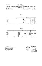
Method of and Apparatus for Electrical Conversion and Distribution - Feb 4, 1891
454,622
System of Electric Lighting - Apr 25, 1891
Tesla directly references the above article in the following two lectures:
EXPERIMENTS WITH ALTERNATE CURRENTS OF VERY HIGH FREQUENCY AND THEIR APPLICATION TO METHODS OF ARTIFICIAL ILLUMINATION
Lecture by N. Tesla before the American Institute of Electrical Engineers at Columbia College, N.Y., May 20, 1891
ON LIGHT AND OTHER HIGH FREQUENCY PHENOMENA
Lecture by Nikola Tesla Delivered before the Franklin Institute, Philadelphia, February 1893, and before the National Electric Light Association, St. Louis, March 1893.
Related Article
PHENOMENA OF ALTERNATING CURRENTS OF VERY HIGH FREQUENCY
Electrical World, Feb 21, 1891
Articles by Tesla
Tesla made public disclosures of means, methods, systems, and apparatus in various articles.
The Inventions, Researches, and Writings of
Nikola Tesla
Thomas Commerford Martin
Tesla's Laboratory Power
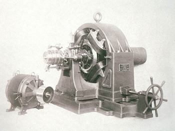
Boiler, Steam Engine, Line-Shaft, Belts & Pulleys
To the Archive Page Discussion on Tesla's Technology
Lab-Tesla Commentary
Nikola Tesla
Tesla's Laboratory Power
Boiler, Steam Engine, Line-Shaft, Belts & Pulleys
To the Archive Page Discussion on Tesla's Technology