487,796
SYSTEM OF ELECTRICAL TRANSMISSION OF POWER - May 15, 1888
UNITED STATES PATENT OFFICE
NIKOLA TESLA, OF NEW YORK, N. Y., ASSIGNOR TO THE TESLA ELECTRIC COMPANY, OF SAME PLACE
Nikola Tesla Patent 487,796 SYSTEM OF ELECTRICAL TRANSMISSION OF POWER
SPECIFICATION forming part of Letters Patent No. 487,796 dated December 13, 1892.
Application filed May 15, 1888. Serial No. 273,992. (No model.)
To all whom it may concern:
Be it known that I, NIKOLA TESLA, a subject of the Emperor of Austria, from Smiljan, Lika, border country of Austria-Hungary, but now residing at New York, in the county and State of New York, have invented certain new and useful Improvements in Systems for Electrical Transmission of Power, of which the following is a specification, reference being had to the drawings accompanying and forming a part of the same.
This invention is an improvement in systems of electrical distribution of power wherein are employed motors having two or more independent energizing-circuits, through which are passed alternating currents differing in phase that are produced by a magneto-electric machine having independent induced circuits, or that are obtained from any other suitable source or by any other suitable means. In illustration of the various conditions which I regard as most important to an attainment of the best results from the use of motors of this character, I have heretofore used generally forms of generator in which the relations of the induced or current-generating coils and field-magnets were such that but two impulses or current are produced in each coil by a single revolution of the armature or field cores. The rate, therefore, at which the different phases or impulses of current in the line-circuits succeeded one another was so little greater than that at which the armature of the generator revolved that without special provision the generator required to be run at very high speed to obtain the best results. It is well known that the most efficient results are secured in the operation of such motors when they are run at high speeds; but as the practicable rate of speed is much limited by mechanical conditions, particularly in the case of large generators, which would be required when a number of motors are run from a single source, I have sought to produce a greater number of current impulses by a slow or slower speed than that at which the ordinary bipolar-machines may be economically operated. I therefore adapt to my system any of the various types of multipolar alternating-current machines which yield a considerable number of current reversals or impulses for each revolution of the armature by observing the main condition essential to the operation of my system that the phases of the currents in the independent induced circuits of the generator should not coincide, but exhibit a sufficient difference in phase to produce the desired results. I may accomplish this in a variety of ways, which, however, vary only in detail, since they are based upon the same underlying principle. For example, to adapt a given type of alternating-current generator I may couple rigidly two complete machines, securing them so that the requisite difference in phase between the currents produced by each will be obtained, or I may secure two armatures to the same shaft within the influence of the same field and with angular displacement that will produce the proper difference in phase between the two currents, or I may secure two armatures to the same shaft with their coils symmetrically disposed, and place two sets of field-magnets at such angle as to secure the same result, or, finally, I may wind on the same armature the two sets of coils alternately, or in such manner that they will develop currents, the phases of which differ in time sufficiently to produce rotation of the motor.
Another feature of my invention is in the plan which I have devised for utilizing generators and motors of this type, whereby a single generator may be caused to run a number of motors either at the same speed as its own or all at different speeds. This I accomplish by constructing the motors with fewer poles than the generator, in which case their speed will be greater than that of the generator, the rate of speed being higher as the number of their poles is relatively less. This will be understood from an example. Suppose the generator has two independent generating-coils which revolve between two pole-pieces oppositely magnetized and that the motor has energizing-coils that produce at any given time two magnetic poles in one element that tend to set up a rotation of the motor. A generator thus constructed yields four impulses or reversals of current by each revolution, two in each of its independent circuits, and I have demonstrated that the effect upon a motor such as that mentioned is to shift the magnetic poles through three hundred and sixty degrees. It is obvious that if the four reversals in the same order could be produced by each half-revolution of the generator the motor would make two revolutions to the generator's one. This would be readily accomplished by adding two intermediate poles to the generator or altering it in any of the other equivalent ways above indicated. The same rule applies to generators and motors with multiple poles. For instance, if a generator be constructed with two circuits, each of which produces twelve reversals of current to a revolution, and these currents be directed through the independent energizing-coils of a motor, the coils of which are so applied as to produce twelve magnetic poles at all times, the rotation of the two will be synchronous; but if the motor-coils produce but six poles the movable element will be rotated twice while the generator rotates once, or if the motor have four poles its rotation will be three times as fast as that of the generator.
This features, so far as it is necessary to an understanding of the invention, are illustrated in the accompanying drawings.
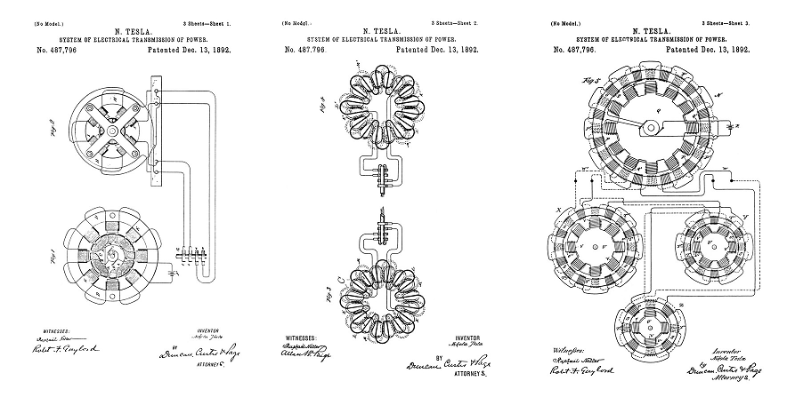
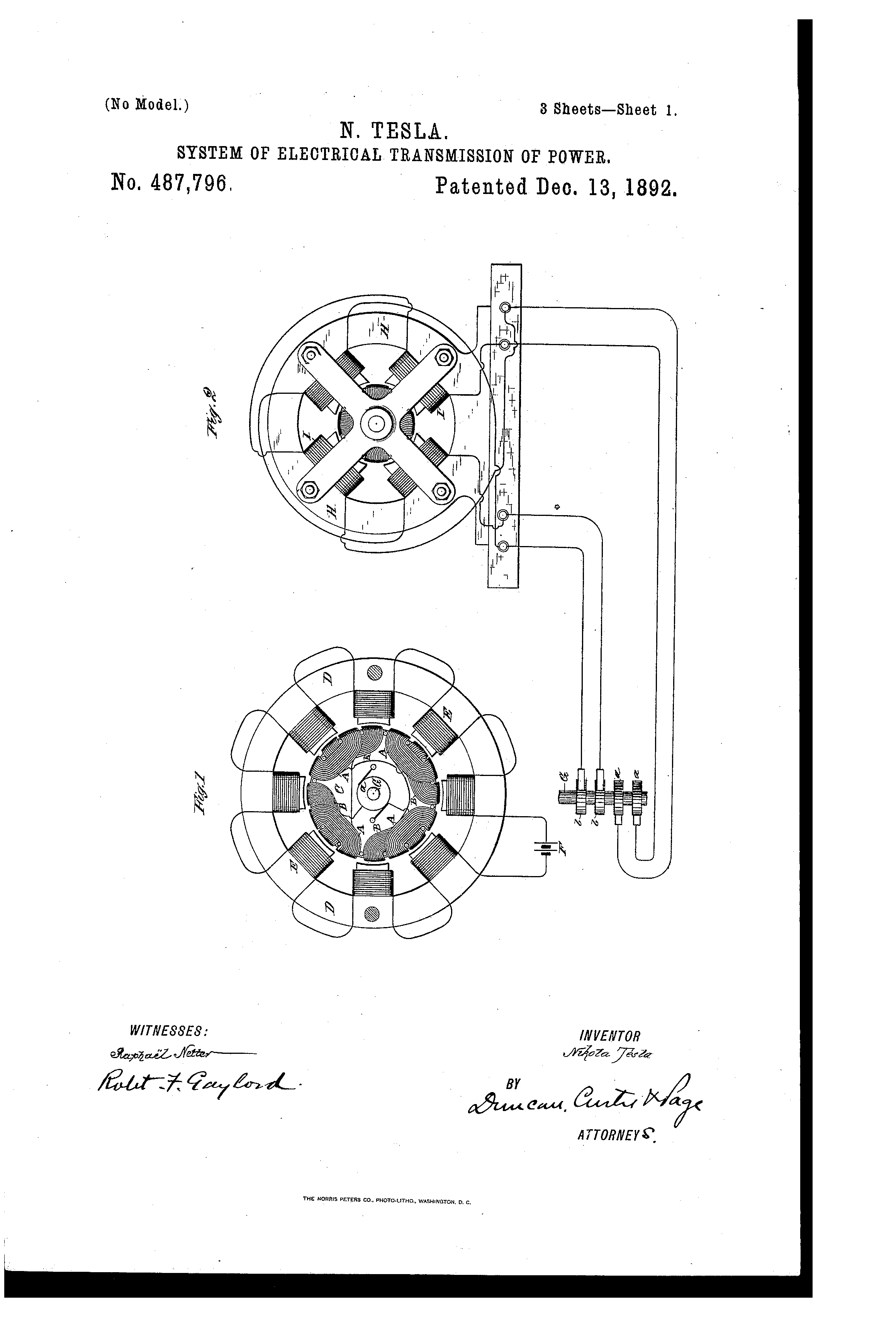
Figure 1 is a diagrammatic illustration of a generator constructed in accordance with my invention. Fig. 2 is a similar view of a correspondingly-constructed motor. Fig. 3 is a diagram of a generator of modified construction. Fig. 4 is a diagram of a motor of corresponding character. Fig. 5 is a diagram of a system containing a generator and several motors adapted to run at various speeds.
In Fig. 1, let C represent a cylindrical armature-core wound longitudinally with insulated coils A A, which are connected up in series, the terminals of the series being connected to collecting-rings a a on the shaft G. By means of this shaft the armature is mounted to rotate between the poles of an annular field-magnet D, formed with polar projections wound with coils E, that magnetize the said projections. The coils E are included in the circuit of a generator F, by means of which the field-magnet is energized. If thus constructed, the machine is a well-known form of alternating-current generator. To adapt it to my system, however, I wind on armature C a second set of coils B B intermediate to the first, or, in other words, in such positions that while the coils of one set are in the relative positions to the poles of the field-magnet to produce the maximum current those of the other set will be in the position in which they produce the minimum current. The coils B are connected, also, in series and to two collecting-rings b b, secured generally to the shaft at the opposite end of the armature.
The motor shown in Fig. 2 has an annular field-magnet H, with four pole-pieces wound with coils I. The armature is constructed similarly to that of the generator, but with two sets of two coils in closed circuits to correspond with the reduced number of magnetic poles in the field.
From the foregoing it is evident that one revolution of the armature of the generator producing eight current impulses in each circuit will produce two revolutions of the motor-armature.
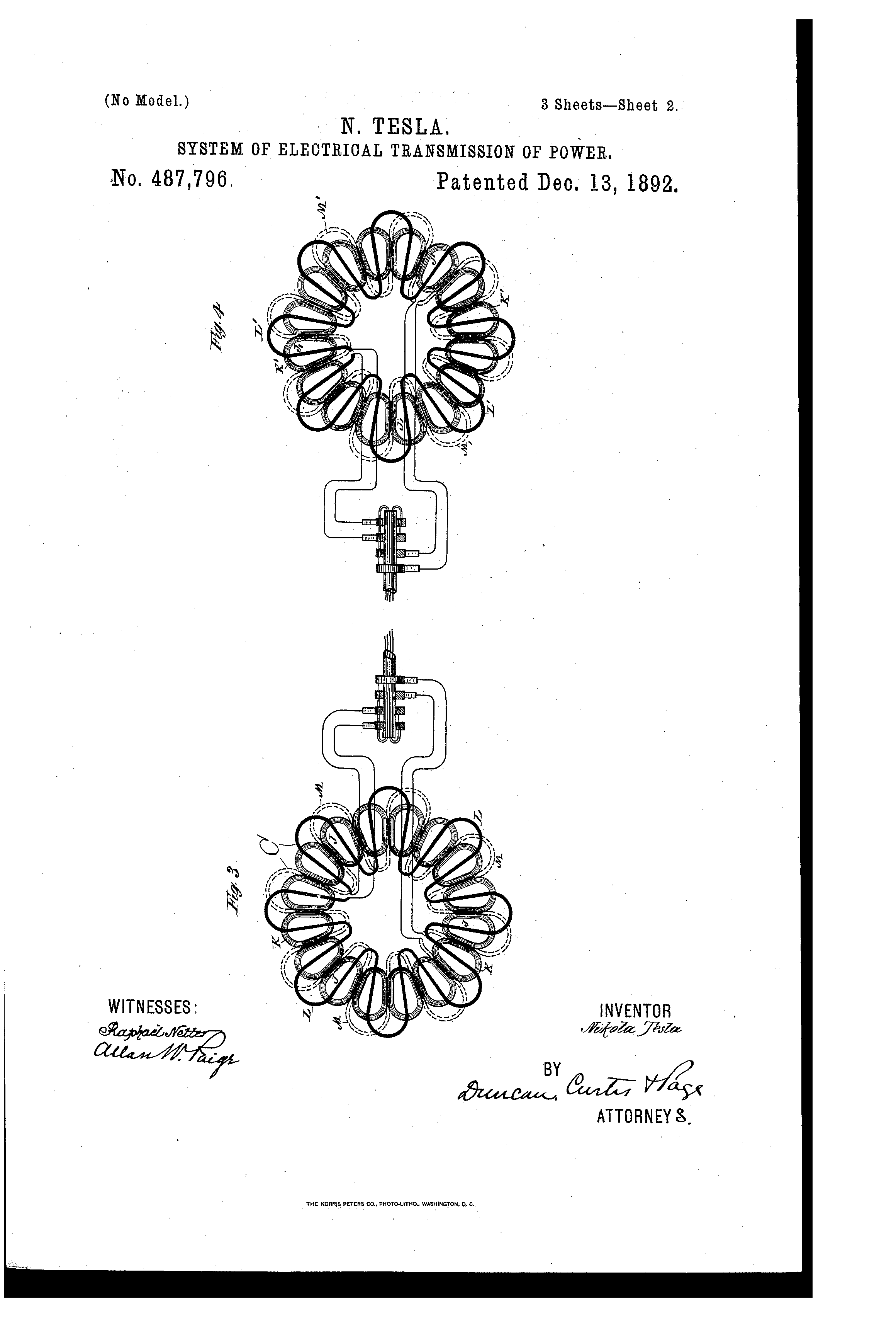
The application of the principle of this invention is not confined to any particular form of machine. In Figs. 3 and 4 a generator and motor of another well-known type are shown. In Fig. 3, J J are magnets disposed in a circle and wound with coils K, which are in circuit with a generator which supplies the current that maintains the field of force. In the usual construction of these machines the armature-conductor L is carried by a suitable frame, so as to be rotated in face of the magnets J J or between these magnets and another similar set in face of them. The magnets are energized so as to be of alternately-opposite polarity throughout the series, so that as the conductor C is rotated the current impulses combine or are added to one another, those produced by the conductor in any given position being all in the same direction. To adapt such a machine to my system, I add a second set of induced conductors M, in all respects similar to the first, but so placed with reference to it that the currents produced in each will differ by a quarter-phase. With such relations it is evident that as the current decreases in conductor L it increases in conductor M, and conversely, and that any of the forms of motor invented by me for use in this system may be operated by such generator.
Fig. 4 is intended to show a motor corresponding to the machine in Fig. 3. The construction of the motor is identical with that of the generator, and if coupled thereto it will run synchronously therewith. J' J' are the field-magnets, and K' the coils thereon. L' is one of the armature-conductors and M' the other.
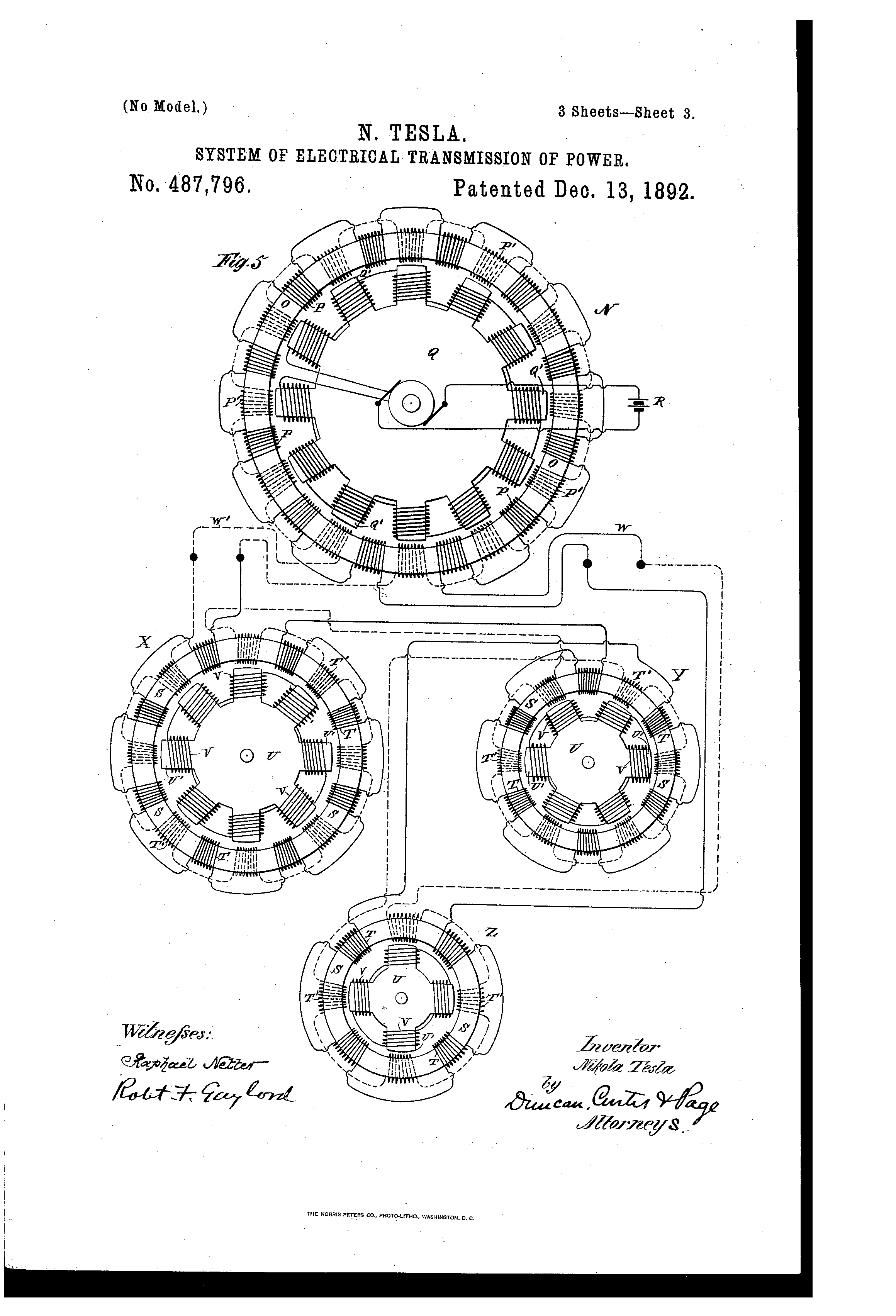
Fig. 5 shows in diagram other forms of machine. The generator N in this case is shown as consisting of a stationary ring O, wound with twenty-four coils P P', alternate coils being connected in series in two circuits. Within these ring is a disk or drum Q, with projections Q' wound with energizing-coils included in circuit with a generator R. By driving this disk or cylinder alternating currents are produced in the coils P and P', which are carried off to run the severals motors.
The motors are composed of a ring or annular field-magnet S, wound with two sets of energizing-coils T T', and armatures U, having projections U' wound with coils V, all connected in series in a closed circuit or each closed independently on itself.
Suppose the twelve generator-coils P are wound alternately in opposite directions, so that any two adjacent coils of the same set tend to produce a free pole in the ring O between them and the twelve coils P' to be similarly wound. A single revolution of the disk or cylinder Q, the twelve polar projections of which are of opposite polarity, will therefore produce twelve current impulses in each of the circuits W W'. Hence the motor X, which has sixteen coils or eight free poles, will make one and a half turns to the generator's one. The motor Y, with twelve coils or six poles, will rotate with twice the speed of the generator, and the motor Z, with eight coils or four poles, will revolve three times as fast as the generator. These multipolar motors have a peculiarity which may be often utilized to great advantage. For example, in the motor X, Fig. 5, the eight poles may be either alternately opposite or there may be at any given time alternately two like and two opposite poles. This is readily attained by making the proper electrical connections. The effect of such a change, however, would be the same as reducing the number of poles one-half, and thereby doubling the speed of any given motor. In these and other respects it will be seen that the invention involves many important and valuable features.
It is obvious that the electrical transformers described in prior patents to me and which have independent primary currents may be used with the generators herein described.
It may be stated with respect to the devices hereinafter set forth that the most perfect and harmonious action of the generators and motors is obtained when the numbers of the poles of each are even and not odd. If this is not the case, there will be a certain unevenness of action which is the less appreciable as the number of poles is greater; but even this may be in a measure corrected by special provisions which it is not here necessary to explain. It also follows, as a matter of course, and from the above it is obvious, that if the number of the poles of the motor be greater than that of the generator the motor will revolve at a slower speed than the generator.
What I claim as my invention is—
1. The combination, with an alternating-current generator comprising independent armature-circuits formed by conductors alternately disposed, so that the currents developed therein will differ in phase, and field-magnet poles in excess of the number of armature-circuits, of a motor having independent energizing-circuits connected to the armature-circuits of the generator, substantially as set forth.
2. The combination, with a source of alternating currents which differ in phase and comprising a rotating magneto-electric machine yielding a given number of current impulses or alternations for each turn or revolution, of a motor or motors having independent energizing-circuits through which the said currents are caused to flow, and poles which in number are less than the number of current impulses produced in each motor-circuit by one turn or revolution of the magneto-machine, as set forth.
3. The combination, with a multipolar alternating-current machine having independent induced or current-generating circuits, of motors having independent energizing-circuits and a smaller number of poles than the generator, as set forth.
4. The combination, with an alternating-current generator having independent induced circuits and constructed or adapted to produce a given number of current impulses or alternations for each turn or revolution, of motors having corresponding energizing-circuits and poles which in number are less than the number of current impulses produced in each circuit in a turn or revolution of the generator, as set forth.
NIKOLA TESLA
Click images for higher-resolution
Source File: US Patent 487,796 - pdf
Chapter VI - The Martin Book
Method of Obtaining Desired Speed of Motor or Generator
Thomas Commerford Martin
With the object of obtaining the desired speed in motors operated by means of alternating currents of differing phase, Mr. Tesla has devised various plans intended to meet the practical requirements of the case, in adapting his system to types of multipolar alternating current machines yielding a large number of current reversals for each revolution.
For example, Mr. Tesla has pointed out that to adapt a given type of alternating current generator, you may couple rigidly two complete machines, securing them together in such a way that the requisite difference in phase will be produced; or you may fasten two armatures to the same shaft within the influence of the same field and with the requisite angular displacement to yield the proper difference in phase between the two currents; or two armatures may be attached to the same shaft with their coils symmetrically disposed, but subject to the influence of two sets of field magnets duly displaced; or the two sets of coils may be wound on the same armature alternately or in such manner that they will develop currents the phases of which differ in time sufficiently to produce the rotation of the motor.
Another method included in the scope of the same idea, whereby a single generator may run a number of motors either at its own rate of speed or all at different speeds, is to construct the motors with fewer poles than the generator, in which case their speed will be greater than that of the generator, the rate of speed being higher as the number of their poles is relatively less. This may be understood from an example, taking a generator that has two independent generating coils which revolve between two pole pieces oppositely magnetized; and a motor with energizing coils that produce at any given time two magnetic poles in one element that tend to set up a rotation of the motor. A generator thus constructed yields four reversals, or impulses, in each revolution, two in each of its independent circuits; and the effect upon the motor is to shift the magnetic poles through three hundred and sixty degrees. It is obvious that if the four reversals in the same order could be produced by each half-revolution of the generator the motor would make two revolutions to the generator's one. This would be readily accomplished by adding two intermediate poles to the generator or altering it in any of the other equivalent ways above indicated. The same rule applies to generators and motors with multiple poles. For instance, if a generator be constructed with two circuits, each of which produces twelve reversals of current to a revolution, and these currents be directed through the independent energizing-coils of a motor, the coils of which are so applied as to produce twelve magnetic poles at all times, the rotation of the two will be synchronous; but if the motor-coils produce but six poles, the movable element will be rotated twice while the generator rotates once; or if the motor have four poles, its rotation will be three times as fast as that of the generator.
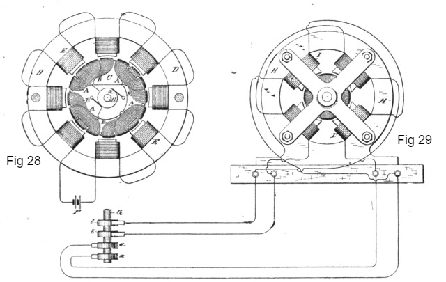
These features, so far as necessary to an understanding of the principle, are here illustrated. Fig. 28 is a diagrammatic illustration of a generator constructed in accordance with the invention. Fig. 29 is a similar view of a correspondingly constructed motor. Fig. 30 is a diagram of a generator of modified construction. Fig. 31 is a diagram of a motor of corresponding character. Fig. 32 is a diagram of a system containing a generator and several motors adapted to run at various speeds.
In Fig. 28, let C represent a cylindrical armature core wound longitudinally with insulated coils A A, which are connected up in series, the terminals of the series being connected to collecting-rings a a on the shaft G. By means of this shaft the armature is mounted to rotate between the poles of an annular field-magnet D, formed with polar projections wound with coils E, that magnetize the said projections. The coils E are included in the circuit of a generator F, by means of which the field-magnet is energized. If thus constructed, the machine is a well-known form of alternating-current generator. To adapt it to his system, however, Mr. Tesla winds on armature C a second set of coils B B intermediate to the first, or, in other words, in such positions that while the coils of one set are in the relative positions to the poles of the field-magnet to produce the maximum current, those of the other set will be in the position in which they produce the minimum current. The coils B are connected, also, in series and to two connecting-rings, secured generally to the shaft at the opposite end of the armature.
The motor shown in Fig. 29 has an annular field-magnet H, with four pole-pieces wound with coils I. The armature is constructed similarly to the generator, but with two sets of two coils in closed circuits to correspond with the reduced number of magnetic poles in the field. From the foregoing it is evident that one revolution of the armature of the generator producing eight current impulses in each circuit will produce two revolutions of the motor-armature.
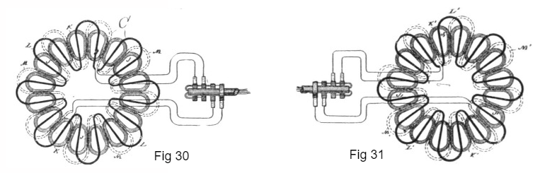
The application of the principle of this invention is not, however, confined to any particular form of machine. In Figs. 30 and 31 a generator and motor of another well-known type are shown. In Fig. 30, J J are magnets disposed in a circle and wound with coils K, which are in circuit with a generator which supplies the current that maintains the field of force. In the usual construction of these machines the armature-conductor L is carried by a suitable frame, so as to be rotated in face of the magnets J J, or between these magnets and another similar set in front of them. The magnets are energized so as to be of alternately opposite polarity throughout the series, so that as the conductor C is rotated the current impulses combine or are added to one another, those produced by the conductor in any given position being all in the same direction. To adapt such a machine to his system, Mr. Tesla adds a second set of induced conductors M, in all respects similar to the first, but so placed in reference to it that the currents produced in each will differ by a quarter-phase. With such relations it is evident that as the current decreases in conductor L it increases in conductor M, and conversely, and that any of the forms of Tesla motor invented for use in this system may be operated by such a generator.
Fig. 31 is intended to show a motor corresponding to the machine in Fig. 30. The construction of the motor is identical with that of the generator, and if coupled thereto it will run synchronously therewith. J' J' are the field-magnets, and K' the coils thereon. L' is one of the armature-conductors and M' the other.
Fig. 32 shows in diagram other forms of machine. The generator N in this case is shown as consisting of a stationary ring O, wound with twenty-four coils P P', alternate coils being connected in series in two circuits. Within this ring is a disc or drum Q, with projections Q' wound with energizing-coils included in circuit with a generator R. By driving this disc or cylinder alternating currents are produced in the coils P and P', which are carried off to run the several motors.
The motors are composed of a ring or annular field-magnet S, wound with two sets of energizing-coils T T', and armatures U, having projections U' wound with coils V, all connected in series in a closed circuit or each closed independently on itself.
Suppose the twelve generator-coils P are wound alternately in opposite directions, so that any two adjacent coils of the same set tend to produce a free pole in the ring O between them and the twelve coils P' to be similarly wound. A single revolution of the disc or cylinder Q, the twelve polar projections of which are of opposite polarity, will therefore produce twelve current impulses in each of the circuits W W'. Hence the motor X, which has sixteen coils or eight free poles, will make one and a half turns to the generator's one. The motor Y, with twelve coils or six poles, will rotate with twice the speed of the generator, and the motor Z, with eight coils or four poles, will revolve three times as fast as the generator. These multipolar motors have a peculiarity which may be often utilized to great advantage. For example, in the motor X, Fig. 32, the eight poles may be either alternately opposite or there may be at any given time alternately two like and two opposite poles. This is readily attained by making the proper electrical connections. The effect of such a change, however, would be the same as reducing the number of poles one-half, and thereby doubling the speed of any given motor.

It is obvious that the Tesla electrical transformers which have independent primary currents may be used with the generators described. It may also be stated with respect to the devices we now describe that the most perfect and harmonious action of the generators and motors is obtained when the numbers of the poles of each are even and not odd. If this is not the case, there will be a certain unevenness of action which is the less appreciable as the number of poles is greater; although this may be in a measure corrected by special provisions which it is not here necessary to explain. It also follows, as a matter of course, that if the number of the poles of the motor be greater than that of the generator the motor will revolve at a slower speed than the generator.
In this chapter, we may include a method devised by Mr. Tesla for avoiding the very high speeds which would be necessary with large generators. In lieu of revolving the generator armature at a high rate of speed, he secures the desired result by a rotation of the magnetic poles of one element of the generator, while driving the other at a different speed. The effect is the same as that yielded by a very high rate of rotation.
In this instance, the generator which supplies the current for operating the motors or transformers consists of a subdivided ring or annular core wound with four diametrically-opposite coils, E E', Fig. 33. Within the ring is mounted a cylindrical armature-core wound longitudinally with two independent coils, F F', the ends of which lead, respectively, to two pairs of insulated contact or collecting rings, D D' G G', on the armature shaft. Collecting brushes d d' g g' bear upon these rings, respectively, and convey the currents through the two independent line-circuits M M'. In the main line there may be included one or more motors or transformers, or both. If motors be used, they are of the usual form of Tesla construction with independent coils or sets of coils J J', included, respectively, in the circuits M M'. These energizing-coils are wound on a ring or annular field or on pole pieces thereon, and produce by the action of the alternating currents passing through them a progressive shifting of the magnetism from pole to pole. The cylindrical armature H of the motor is wound with two coils at right angles, which form independent closed circuits.
If transformers be employed, one set of the primary coils, as N N, wound on a ring or annular core is connected to one circuit, as M', and the other primary coils, N N', to the circuit M. The secondary coils K K' may then be utilized for running groups of incandescent lamps P P'.
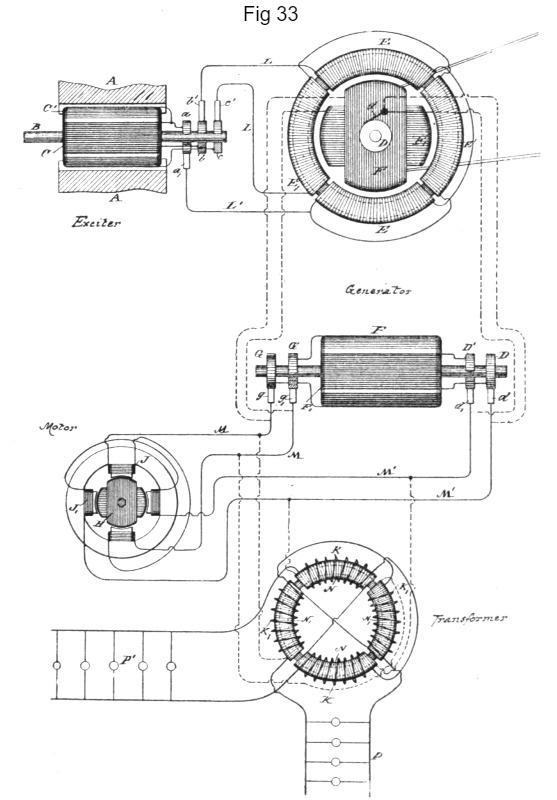
With this generator an exciter is employed. This consists of two poles, A A, of steel permanently magnetized, or of iron excited by a battery or other generator of continuous currents, and a cylindrical armature core mounted on a shaft, B, and wound with two longitudinal coils, C C'. One end of each of these coils is connected to the collecting-rings b c, respectively, while the other ends are both connected to a ring, a. Collecting-brushes b' c' bear on the rings b c, respectively, and conductors L L convey the currents therefrom through the coils E and E of the generator. L' is a common return-wire to brush a'. Two independent circuits are thus formed, one including coils C of the exciter and E E of the generator, the other coils C' of the exciter and E' E' of the generator. It results from this that the operation of the exciter produces a progressive movement of the magnetic poles of the annular field-core of the generator, the shifting or rotary movement of the poles being synchronous with the rotation of the exciter armature. Considering the operative conditions of a system thus established, it will be found that when the exciter is driven so as to energize the field of the generator, the armature of the latter, if left free to turn, would rotate at a speed practically the same as that of the exciter. If under such conditions the coils F F' of the generator armature be closed upon themselves or short-circuited, no currents, at least theoretically, will be generated in these armature coils. In practice the presence of slight currents is observed, the existence of which is attributable to more or less pronounced fluctuations in the intensity of the magnetic poles of the generator ring. So, if the armature-coils F F' be closed through the motor, the latter will not be turned as long as the movement of the generator armature is synchronous with that of the exciter or of the magnetic poles of its field. If, on the contrary, the speed of the generator armature be in any way checked, so that the shifting or rotation of the poles of the field becomes relatively more rapid, currents will be induced in the armature coils. This obviously follows from the passing of the lines of force across the armature conductors. The greater the speed of rotation of the magnetic poles relatively to that of the armature the more rapidly the currents developed in the coils of the latter will follow one another, and the more rapidly the motor will revolve in response thereto, and this continues until the armature generator is stopped entirely, as by a brake, when the motor, if properly constructed, runs at the speed with which the magnetic poles of the generator rotate.
The effective strength of the currents developed in the armature coils of the generator is dependent upon the strength of the currents energizing the generator and upon the number of rotations per unit of time of the magnetic poles of the generator; hence the speed of the motor armature will depend in all cases upon the relative speeds of the armature of the generator and of its magnetic poles. For example, if the poles are turned two thousand times per unit of time and the armature is turned eight hundred, the motor will turn twelve hundred times, or nearly so. Very slight differences of speed may be indicated by a delicately balanced motor.
Let it now be assumed that power is applied to the generator armature to turn it in a direction opposite to that in which its magnetic poles rotate. In such case the result would be similar to that produced by a generator the armature and field magnets of which are rotated in opposite directions, and by reason of these conditions the motor armature will turn at a rate of speed equal to the sum of the speeds of the armature and magnetic poles of the generator, so that a comparatively low speed of the generator armature will produce a high speed in the motor.
It will be observed in connection with this system that on diminishing the resistance of the external circuit of the generator armature by checking the speed of the motor or by adding translating devices in multiple arc in the secondary circuit or circuits of the transformer the strength of the current in the armature circuit is greatly increased. This is due to two causes: first, to the great differences in the speeds of the motor and generator, and, secondly, to the fact that the apparatus follows the analogy of a transformer, for, in proportion as the resistance of the armature or secondary circuits is reduced, the strength of the currents in the field or primary circuits of the generator is increased and the currents in the armature are augmented correspondingly. For similar reasons the currents in the armature-coils of the generator increase very rapidly when the speed of the armature is reduced when running in the same direction as the magnetic poles or conversely.
It will be understood from the above description that the generator-armature may be run in the direction of the shifting of the magnetic poles, but more rapidly, and that in such case the speed of the motor will be equal to the difference between the two rates.
Previous Chapter --- Contents --- Next Chapter
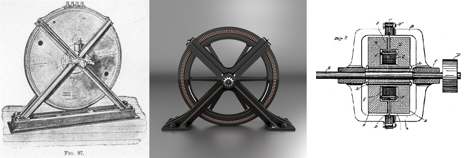
These diagrams represent the generator designs that were finalized by Westinghouse and were applied on large scale in the Machinery Hall at the 1893 World's Fair.
To the Archive Page Discussion on Tesla's Technology

Lab-Tesla disclosures on the technology just presented
A NEW SYSTEM OF ALTERNATE CURRENT MOTORS AND TRANSFORMERS
Paper by Nikola Tesla read to the American Institute of Electrical Engineers on May 16, 1888
EXPERIMENTS WITH ALTERNATE CURRENTS OF VERY HIGH FREQUENCY AND THEIR APPLICATION TO METHODS OF ARTIFICIAL ILLUMINATION