High Performance Tesla Coils
coilbld.zip - 12-3-1995
https://lab-tesla.org/pdf/coilbld.zip
Mirror of: https://www.nic.funet.fi/pub/sci/electrical/tesla/misc/coilbld.zip -- July 25, 1996
Mirror of: http://www.capturedlightning.org/hot-streamer/stk/tc/coilbld.htm - 2008
Great resource of Tesla material: https://www.nic.funet.fi/pub/sci/electrical/tesla/ <- Start with the 00README file, then check out the misc directory ;)
1) The first step in winding a coil is to select a coil form. The coil form should be a low loss material (we are talking about radio frequency losses in the 50 - 1000 kHz range) like polyethylene, polystyrene, polypropylene, polycarbonate (Lexan), acrylic (Plexiglas), or even ABS: but the most common material used from the standpoint of cost and availability is PVC (poly-vinyl-chloride), which is VERY HIGH LOSS. PVC may be used if the material is properly prepared before winding on wire. Regardless of the material selected, the thinnest possible coil form should be used; avoid heavy walled or pressure rated tubing.
The ratio between the actual winding length and diameter is important. The ratio of the winding length to the winding diameter is known as the ASPECT RATIO (height : diameter), where the diameter always equals 1. Aspect ratios may be expressed by a single number such as "3.21". Please review the simple chart below when selecting a coil form and the proper wire gauge: (All dimensions are in U.S.A. measurements, inches, feet, AWG, etc..)
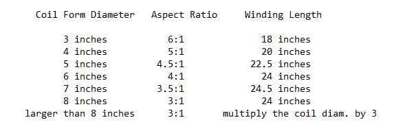
This chart is based upon the physical characteristics of the actual winding. Do not assume that "six inch PVC drain pipe" actually measures six inches o.d., and be sure to allow a few inches of extra coil form length. When selecting and cutting the coil form you should allow at least an extra inch of coil form on each end, and I generally figure on cutting the coil form three inches longer than the actual winding length. After determining the length of the coil form required, measure twice, then cut. Make sure that both cut ends are square.
2) The coil form must be free of major surface imperfections. I wet sand my coil forms with #150 wet/dry sandpaper (or emory cloth) and water to remove markings, oxidation, scratches and cuts. After wet sanding, the coil form must be dried thoroughly. If PVC plastic is used the coil form should be dried in a drying box, gently baked under a heat lamp, or even placed in a very low temperature oven for a few days. PVC coil forms must then be sealed to negate the high RF loss factors that are inherent to this plastic. Sealing also prevents PVC plastic from reabsorbing moisture. Using a sealer such as petroleum based polyurethane varnish, two-part clear epoxy paint, and some acrylic spray sealers is important. Avoid water based and milky "emulsion" type sealers.
When I am ready to seal a PVC coil form, I mount the form up on a winding spindle. I work in a well ventilated area, and I turn on at least one fan to keep air moving over the work. I set up a few heat lamps or other spark-free radiant heat source. Then I begin a four hour coating process. I prefer a high-gloss polyurethane or epoxy sealer applied with a good varnish brush. Sealer is slopped on while the coil form is spun. I use the brush to apply and smooth the heavy coats, and to spread out drips and runs. Coats may be applied almost continuously in this fashion for an hour or two. After coating the coil form, it should be rotated on the winding spindle for a few hours while radiant heat and moving air are used to speed a cure. Using this method it is possible to build up a high-gloss finish which is free of runs, drips, and sags. If drips and sags do occur, they can be "grated" off with a body putty grater, or carefully trimmed away with a knife while the sealant is still pliable.
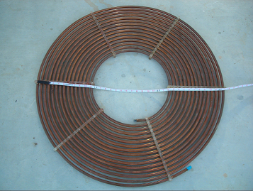
3) The coil should be close wound with a good quality magnet wire. I use double Formvar enamel coated magnet wire purchased surplus, but newer insulations such as Polyimide coatings are even better. Magnet wire gives the maximum inductance per unit volume of coil form. The coil should have over 800 turns, but not too many over 1000 turns. There is a little leeway here. Use the thickest gauge of magnet wire that will allow the correct aspect ratio, and between 800 - 1000 turns. It has been suggested that all coils be wound with at least No. 22 AWG, or larger, magnet wire. I would concur with this recommendation.
I plug the ends of the coil form with a tight fitting wooden disk and run a dowel or threaded rod through a center hole so that it will spin. I set up the wire spool so that it will spin at one end of a pair of sawhorses, with the coil form at the other end. I wind the wire on by hand, making sure the windings are close-wound, tight, smooth, and even. Overlaps and gaps will adversely affect the performance. I use a dab of hot glue, epoxy, or tape to hold the first turns in place, and I make sure to leave a 3 foot tail of wire at both ends. Do not drill holes or permanently route wire inside of the coil form.
ROUGH FREQUENCY CALCULATIONS:
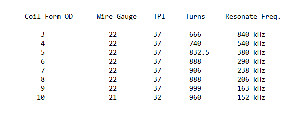
You can see by reading through the text and looking at the charts that some design problems occur in coils with a small outside diameter. Coils under five inches in diameter must make sacrifices: either they must get long and skinny to obtain a sufficient number of turns; or they must be wound with smaller diameter wire. When making this decision, after determining that a larger diameter coil will not be satisfactory, it must be understood that 75% of the voltage produced by a 1/4 wave Tesla secondary results from pure resonance; meaning that the "ratio of turns transformation" calculated with the primary coil is not responsible for the majority of voltage gains: go with heavier wire as I have indicated rather than additional turns. On small diameter coils the aspect ratio may be increased somewhat rather than sacrifice turns or wire diameter.
4) Once the coil is wound, it is sealed to prevent corona leakage and to help protect against electrical breakdown between turns. Sealing also prevents the windings from loosening up on the coil form. I use the same sealers mentioned earlier, those being petroleum based polyurethane, two-part clear epoxy paint, or water free acrylic. Coats of sealer are applied with a brush or spray until there are no ridges and valleys in the wire. In other words the coats must build up until the wire is completely imbedded in sealer. A fan and radiant heat source may be used as required to speed the cure rate of the sealer. Rotating the coil on the winding spindle will aid in obtaining a smooth coating that is free of runs and drips.
5) Two plastic disks are cut to match the ends of the coil form. The plastic should be approximately the same thickness as the coil form walls. Experience shows that plexiglas is both readily available and works quite well in this application. Dry fit and file the caps as necessary until a good match is made to the coil form ends. I rough up, or score, the matching surface of the plastic disks where they will be bonded to the ends of the coil form. This provides a surface around the edges to give the epoxy adhesive a bite.
6) Make sure all surfaces are dry, clean, and free of oil. Place a bead of fresh, good quality, clear two-part epoxy adhesive around the top of the coil form and the matching end cap, then cap the end of the coil with the plastic disk. Weight the end cap down until the epoxy has cured; then flip the coil over and repeat the procedure to cap the other end. I will stop here to make an important note:
NO HOLES ARE EVER DRILLED INTO THE SIDEWALL OF THE COIL FORM!
WIRE IS NEVER ALLOWED TO ENTER INSIDE OF THE COIL!
Ideally the secondary coil should be hermetically sealed. This prevents internal electrical breakdowns of the coil and prevents the uptake of moisture into the coil form when PVC plastic pipe is used. If holes are drilled into the coil sidewalls, and/or, the wire is allowed to enter inside of the coil, then spark lengths that exceed the length of the winding will almost surely cause the coil to fail. Once a coil has failed in this manner it is not repairable. One small hole may be drilled into the bottom end plate to allow the air pressure to equalize, but under no circumstances should any other holes be drilled.
This series of diagrams shows details of the coil base and the steps required to construct a high current ground terminal without drilling into the coil form or permanently mounting protruding hardware.
7) The first step in constructing a high current ground terminal is to cut out a rectangle in the sealer at the base of the coil form just below the winding. The coil winding should end just above one corner of scribed area. The cut should be about two inches long and one inch high, minimum. This section of sealer is then peeled and scraped away to expose the bare plastic coil form. Use a blade and deeply score and cut the bared plastic in a "cross-hatch" pattern.
8) Cut a strip of copper from some heavy copper sheet. The strip of copper should fit inside of, and almost fill, the cleared and scored area on the coil base. Round the corners of the copper strip, then bend the strip gently until it conforms exactly to the curvature of the coil form. The rounded and curved strip of copper should fit neatly on the coil form in the prepared area. If copper sheet is not available the ground terminal may be constructed by splitting open a section of copper water pipe and peening out the proper shaped terminal.
9) This next step requires a piece of steel (with a flat surface) and a small hammer. Gently pull the base wire of the coil free from the sealer. Pull the wire up all the way to the beginning of the winding. Once freed, trim this wire, leaving a 2-1/2 inch length. Scrape the base wire clean of all sealer and enamel insulation.
Next, carefully wrap some heavy plastic or cardboard around the coil to protect the winding from dings, but leave the base wire extended and exposed. Position the coil so that the base wire may be laid out flat on a small steel block or plate, then gently peen the wire out with a small hammer. Copper wire is very malleable, it will be possible to peen the round wire into a thin flat strip. Trim the length again if required.
10) Clean and tin the inside curved surface of the copper strip. Clean and tin the peened out base wire from the coil. Using a clothes-pin, or other small clamp, position the flattened base wire diagonally across the inside curve of the copper strip. Solder the two together with a very hot iron. Avoid clumps or blobs of excess solder. Clean the soldered area thoroughly with solvent to remove all traces of rosin, oil, and dirt. Sand the soldered area gently with abrasive paper to smooth out any rough areas and high spots. Clean the soldered area a second time.
11) Using a cloth or lint-free wipe, clean the scored rectangle on the coil form base with solvent, carefully removing all traces of oil and dirt. Wipe down the copper ground terminal one last time. Prepare some strips of waxed paper and an assortment of rubber bands. Mix up a small batch of clear, two-part epoxy. Smear the scored rectangle on the coil form with epoxy, then smear the inside curve of the copper ground terminal. Fit the ground terminal into place, cover with strips of wax paper, and secure with a couple of rubber bands around the coil form. Allow sufficient time for the epoxy to gel firmly, but do not allow a complete cure. Remove the rubber bands and the wax paper strips. Gently scrape away excess epoxy from the surface of the copper ground terminal, then wipe the terminal surface clean with solvent.
If attention has been paid to detail and technique, the copper ground plate should be nearly flush and firmly attached to the bottom of the coil form just below the winding. Sometimes it may be necessary to fill in a low spot or two with a second tiny batch of epoxy.
12) This figure shows how effective this ground terminal is in practice. It is quite easy to connect one inch SMOOTH grounding strap directly to the base of the coil with a couple of rubber bands or a long strip of electrical tape. This connection is ideal for removing the heavy RF current produced at the base of the coil. This ground terminal is also nice in that it may be quickly connected and disconnected, offering flexibility and ease of setup. This system is also efficient if the base terminal is to be used to feed RF current into the bottom of the coil, as in the extra coil of the Tesla Magnifier.
Being flush mounted without drilling holes into the coil form, this terminal preserves the electrical strength of a sealed coil form. Without protuberances typical of other terminal types, there is nothing to break off or damage. The same lack of protuberances makes it easy to store several coils close together without worry of scratching or cutting the finishes. This terminal is clean and professional looking.
13) If the preceding directions have been adhered to, the completed Tesla coil (RF resonator) will closely resemble the diagram in figure 13. The coil form is hermetically sealed. There are no holes into the wall of the coil form. The wire never enters inside of the coil and all connections are made externally where they do not compromise the electrical integrity of the construction. The base wire has been cut, peened, and connected to a high current ground terminal. The other end of the coil, the air terminal, has been left untrimmed.
14) This shows how the air and ground connections are made to the completed coil. A stand-off insulator is placed on the top of the coil. A TOROID discharge terminal is placed on the insulator and the wire is air-wound around until it contacts with the bottom plate of the conductive toroid. These air wound turns are widely spaced, but the diameter is kept as close as possible to that of the secondary winding. Once contact has been made to the bottom of the toroid, the wire may be held in place with a small piece of tape, then the winding is discontinued and a bared section of wire is connected directly to the center of the toriod with a nut and bolt clamp, tape, etc.. Excess length may now be trimmed.
The exact length of the stand-off insulator, and therefore the height the toroid discharge terminal sits above the secondary resonator, can only be determined by experiment. This varies with the size of the toroid, the size of the coil, and the input power into the system. Due to the number of factors involved, this insulator may require frequent adjustments/changes. For this reason I do not permanently mount a stand-off insulator on the coil. I keep a selection of square cut sections of PVC plastic pipe that I use for stand-off insulators. The toroid is electrically connected as indicated above, then it is simply set on top of a PVC pipe stand-off insulator. The system is now ready to be fired. If desired, after some experimentation, the insulator can be permanently mounted: the end cap should be scored with a sharp tool, not drilled; the surface should be prepared, and the insulator should be glued in place with two-part epoxy.
The ground connection is made via the shortest available path, using the heaviest, widest possible SMOOTH conductor, to a dedicated RF ground constructed specifically for Tesla work. This ground is referred to as the "system RF ground" or simply the "system ground". The system ground is usually constructed, not happened upon. I advise constructing a system ground from scratch unless you can verify that any available grounds are electrically isolated. Do not use a water pipe. Do not use the house ground. Tesla rated grounds need to be extremely heavy, usually comprising of several eight to ten foot copper pipes hammered into the ground. The pipes should be separated in the ground by their lengths (eight foot pipes are set eight feet apart) and connected with one inch smooth strap buried below sod level.
It should be noted that these instructions are designed to produce a highly efficient RF resonator with exceptional electrical strength at the lowest possible cost. Coils built to these specifications are capable of producing, and withstanding, discharge lengths that exceed the physical length of the coil by a factor of 3.5 or more. These instructions are the product of years of experimentation winding dozens and dozens of coils and with the collaboration of others in the field of high powered Tesla systems. This design method has been repeatedly tested and reproduced by beginners with excellent results.
FREQUENTLY ASKED QUESTIONS
>> How would someone go about drying a PVC or similarly hygroscopic material before it was to be sealed? In the oven? What temp? Is the interior of the form sealed as well?
Before I get to the drying stage, I go ahead and wet sand the coil form with abrasive paper or emory cloth. I use a #150 grade of abrasive and sand with water until all printing, oxidation, and major dings (cuts and scratches) are removed.
One of the best ways to dry this plastic is to get a large cardboard box. Cut a few small vent holes in the top and bottom of the box. Thread some string or light cord through the top of the box to form a sling to hold the coil form. You will need two or three loops of cord inside the box to securely suspend the coil form near the top vent holes.
Place a light bulb on a heat resistant insulator inside the box directly below the coil form. Depending on the ambient temperature, the size of the box, and the number of vent holes, the wattage (or number) of bulbs may be varied.
The heat from the bulb(s) will produce a warm air convection inside of the box that will effectively dry the coil form over a period of no more than three days. The temperature does not need to be very high, temperatures between 120 - 150 degrees F are just fine.
Once removed from the drying box, the outside of the coil form should be sealed immediately, then wound with wire. Once the coil form is wound, the ends of the coil form are capped with plastic disks glued down with epoxy to form a hermetic seal.
However, if the coil form is removed from the drying box and winding is delayed for some reason, one coat of sealer should be applied to the inside of the coil form to prevent moisture from reabsorbing. If the winding proceeds at an orderly pace without delays, then the end caps will prevent air exchanges which removes the need to seal the inside surface of the coil form.
>> Besides polyurethane what is a good sealer for a secondary coil form and and where do I get this sealer?
Quoting Chip Atkinson:
The coating that I used is called
Super Gloss
Build 50
by Behr.
I got it at the hardware store. (Hugh M. Woods, aka Payless Cashways) It is in two paint cans, shrink wrapped together. The can wrappers are orange. The stuff is stocked in the varnish section, right next to the polyurethane. The potential problems are bubbles, which didn't seem to make much of a difference for me, and annular bulges. The bulges appear if you don't get the coating on evenly and the form is turning. I would not recommend using Build 50 as a coating unless you feel confident in your abilities to apply it smoothly and evenly. I ended up with some bulging, but it doesn't detract from the over all appearance. It would however cause problems if one used it to seal a PVC pipe under the winding. This would make the windings irregular and probably cause the top coat to be very uneven as the stuff bulges and climb towards the high spots as the form turns. Nevertheless, I still recommend Build 50 since it goes on in one coat and is quite tough and hard. Chip Atkinson
>> I got the 8" PVC today. Cost me $7.00 for 3 feet. It is solid wall about 5/16" thick. I am going to setup something to dry it later today. I got a basic polyurethane varnish to coat it with.
You said you did not want to put any holes on the coil form if necessary because of moisture seeping in. What about throwing a couple packets of silica gel in before sealing it up? Or maybe some other dessicant?
No problems here with your coil form material. The coil form could be thinner walled. I always try to use the thinnest walled material possible for my coil forms.
Holes in the coil form are avoided primarily because holes compromise the electrical strength of the construction. The fact that a properly sealed and capped secondary coil prevents re-absorbtion of moisture when using properly dried and prepared PVC is an added bonus. Dessicants such as calcium sulfate, silica gel, etc. will simply trap water. I would not use these dessicants with the idea that these compounds are going to end up as permanent parts of the coil. Dessicants can be employed as part of the drying process if desired, but these compounds should be removed (along with any absorbed moisture) and not left as part of the sealed construction.
>> Oh, how did you cut the plexiglas disks in a circle?
I use a band saw or a jig saw. A plastics dealer will be able to custom cut these disks if required, and the same plastics dealer is usually able to supply the correct blades and cutting advice if you ask.
>> And what about using a Silicon RTV type cement to attach the ends. This stuff is deffinitly non-flamable and is hard to screw-up with.
GOOD QUESTION!
Sounds great does it not..? But... These adhesives leave a residual acetic acid vapor which is trapped inside the coil form. The acetic acid vapor is highly conductive and ionizes readily.
DO NOT USE THESE PRODUCTS in this particular application!
>> A brief suggestion regarding polystyrene as a form material: it is polystyrene as is the plastic used to make model cars. Why not use airplane glue? It will act as a solvent welding activator, is very water and humidity resistant, and if used properly, will resist at least the same temperatures as the form material? I have no idea what the electrical properties are, but it is cheap and possibly worth a try.
I am not exactly sure what you propose using airplane glue for, but I can tell you from experience, you don't want to use this material anywhere on or near a Tesla coil. The bottle is clearly labeled:
"DO NOT USE NEAR SPARK OR FLAME"
If you were to use a solvent based adhesive to cap the ends of the secondary coil form, for instance, and the coil fails internally, the resulting explosion will be hazardous. Trapped solvent fumes mixed with air in a sealed tube provides enough energy for a pretty decent explosion. I have had this happen more than once. The windings will prevent the entire coil form from splitting, but the ends of the coil form between the winding and the cap will shred and throw shards of coil form "shrapnel" about the room. The discharge terminal will be thrown, and you can almost count that it will receive damage when it strikes the floor or the tank circuit.
Nowhere in my instructions do I recommend using solvent based adhesives in the secondary coil construction.
Importing text written by Steve Crawshaw:
I've just intercepted RQ's request for info on secondary coatings, and
I thought I'd throw my info in here. In UK there is a component
distributor called RS Components who supply all sorts of electronics
gear. They have a number of products for HV insulation. I have got
hold of a tin of the following:
Anti Corona Lacquer 569-290 $2.86 400ml Aerosol
This has a dielectric strength of 48Kv/mm with a working temp of up to
150 degrees C. I intend to follow RQ's preparation and sealing method
for secondary construction on a 4.5 inch Diameter Perspex (Lexan)
former, but use this stuff instead of polyurethane.
Unfortunately the perspex has been extruded, not moulded, so there are small striations / lines running along the length of the tube. This is why I intend to wet & dry it before winding. Also being extruded, it is not completely round :( I have some 0.4 mm enammeled Cu winding wire and I have calculated 1150 turns with a 4:1 aspect ratio. On top of this goes my 12" x 3.5" stainless steel toroid. I have just had this shotblasted and it is double sexy. I have silver soldered a 1/16" thick circular steel plate into the centre of this to support the toroid while on top of the coil. I have asked this before, but I can't remember if I got an answer. When constructing the secondary coil, I seem to recall that RQ recommends sealing end caps on the former. Why is this?
Anyway, back to the point in question. There are some more products of
interest in the same section of the RS book:modified silicone conformal coating
90Kv/mm dielectric strength
red and transparent colours
fluoresces under UV (good for tracing corona leakage?)
temperature -70 - 200C
best cure 24 hours @ 100C; 200ml aerosol 494-714 $6.20
Tropicalised varnish
Acrylic varnish with UV tracer
touch dry in 10 mins
recommended drying 24 hours @ 21C + 4 hours @ 60C
temp -60 - 130C
dielectric constant 2-45 @ 10KHz @ 21C
dissipation factor 0.028 @ 10kHz @ 21C
500ml tin 188-627 $6.29
Hope this info is of use. As I say this is a UK source but no doubt there are equivalents in USA. Prices are in pounds sterling but I can't make my keyboard do Pound signs. Cultural imperialism or what?
>> I have asked this before, but I can't remember if I got an answer. When constructing the secondary coil, I seem to recall that RQ recommends sealing end caps on the former. Why is this?
In a high performance design, properly driven, the secondary coil is easily capable of producing spark lengths that greatly exceed the physical height of the secondary coil. In other words, your coil may be 20 inches tall producing sparks that are 30 inches long.
Under these conditions an "open" or uncapped coil will almost certainly fail. All of the electrical failures that I have seen occurred inside of the coil form. The failures resulted in sidewall perforations, arc scoring, and carbonization of the coil form. I have never been able to successfully repair a coil once it has failed in this manner.
To prevent electrical breakdowns in the secondary coil the following points are important:
1) Never drill holes into the sidewall of the coil form.
2) Do not allow wire (or any conductor) inside of the coil form.
3) Both the top & bottom of the coil must be capped air tight.
4) Solvent based adhesives must not be used for capping the coil.
If these simple guidelines are met, the coil will have an enormous electrical strength and failure is highly unlikely. Coils wound on all plastic coil forms that are constructed following the simple guidelines above can produce sparks that exceed the physical winding height by a factor of 5 to 1 without failure or breakdown in the construction.
Every set of printed coil plans that I have seen shows two holes drilled into the coil form sidewall. The wire used to wind the coil is fed through the hole near the intended base. The wire is then routed inside of the coil form to a ground terminal. The coil is wound, and the other end of the wire is fed through the hole near the intended top. The wire is again routed inside of the coil form through an insulator mounted on the top of the coil. If end caps are even used, wood is frequently recommended.
While these instructions will work fine on an open wooden or cardboard coil form that is space wound with d.c.c. (double cotton covered) wire a-la 50 years ago, if followed today using close wound magnet wire on a high-Q plastic form it is lethal.
Modern high-Q construction materials demand a change in construction practices and techniques. A high inductance design (close wound magnet wire on a plastic coil form) will produce a very potent secondary winding which will promptly smoke when coupled to an efficient tank circuit unless care is taken to prevent internal arcing and sidewall failure of the coil form. If the wire is never allowed to enter inside of the coil form, no holes are drilled into the sidewalls, and both ends of the coil form are properly capped, there is no way the spark can get inside of the coil. The result is that the coil will not fail.
BTW, the reason I have recommended that solvent based adhesives NOT be used when capping the coil form is because the explosive vapors are trapped inside of the coil. If points #1-3 are followed then point #4 should not be too critical, but if an internal failure of the secondary coil does occur, you can count on any trapped vapors igniting and an explosion will result. This is not just an idle warning either. I have had it happen and it was nothing but dumb luck that a serious accident did not result.
Question, quoting Ed H:
>> On the subject of coatings: Richard Hull (or TCBOR) mentions in the guide to the Colorado Springs notes that he/they don't use secondary coatings anymore-or at least they were using only a single thin coat.
He says they avoid breakdown from the coil by proper terminal placement.
Any comments on Hull's method?
Yes, Hull's method works just fine. Many times I have test fired a coil with no coating whatsoever. While coating is not an absolute necessity, it is worthwhile for several reasons.
1) Coatings prevent the winding from loosening and slipping off the coil form.
2) Coatings decrease the chances of a coil suffering permanent damage as a result of over-coupling and "splitting".
3) Coatings provide physical protection to the winding and help prevent serious damage to a coil that may result from bumps, dings, cuts, falls, etc..
4) During experimentation a coiler may choose to deliberately over-drive the coil, the coil may be overdriven accidently, or the coil may be fired in unusual configurations where the electrical stress may be high (Tesla Magnifier and bipolar configurations for example). The coating does reduce corona losses and reduces the incidents of electrical breakdowns.
5) A well applied coating looks good, and can be maintained.
I guess the argument here is that if you are winding a coil to become part of a permanent system where changes are rarely or infrequently made (like a museum or display coil) one or two light coats of sealant, or just enough to stick the windings down, would be fine. Once tuned and adjusted with a proper toroid the coil will function well, and without excessive corona losses.
But on the other hand if you are like me; a person who frequently removes/replaces/stores coils, changes primary configurations, gaps, caps, dischargers, fires an occasional Magnifier or bipolar system, etc.. The benefits of a good heavy coating are clear, if for no other reason than protecting the winding from accidental physical abuse.
I have found that the benefits of a heavy coating on the secondary far outweigh the advantages of a light or non- existent coating. Also, there are a lot of beginners out there. Beginners especially need the physical and electrical ruggedness that a heavy coating provides.
If you got this far you are probably seriously interested in this technology and wish to learn more. Please use the following links:
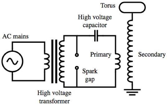
Tesla Coil Primary Design
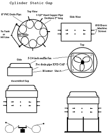
RQ/TCBOR Cylinder Static Gap
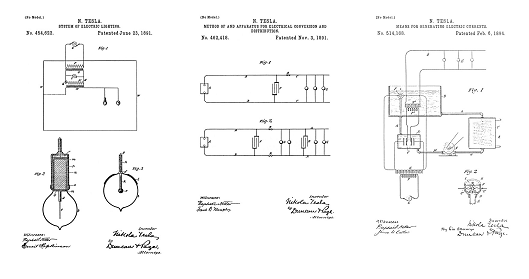
U.S. Patent 454,622
Tesla introduced his resonating coil technology in lecture in 1891
High Performance Tesla Coils -- Top of this page
If you are seriously interested in constructing one of these coils, Lab-Tesla hosts an extensive archive of RAW text containing information on coil design and construction, power supplies, spark gap systems, etc.. Including instructions on how to scavenge and salvage for free and low-cost components. Please click on the link below, this text file is 600K and unedited. It is mirrored at: http://textfiles.com/science/rqmsgs_t
FidoNet Messages - 10KVA Tesla Coil - 1993
https://www.teslacoildesign.com/index.html
https://deepfriedneon.com/tesla_frame1.html
Tesla's Electrical Isochronous Oscillators
Capacitive Discharge Power Processing
Tesla's Electric Circuit Controllers
Precision Switching Technology
Tesla's Laboratory Power