Nikola Tesla's Wireless Receivers
The True Wireless - Nikola Tesla, Electrical Experimenter, May 1919
613,809
Home Appliances and Industrial Solutions
The first lesson is the receivers are cheap and easy. It's the transmitters where all the money and brain sweat goes.
Richard Quick's Experiments with Resonate Receivers - Text file.
Mirror of: rqexps_t.txt @ http://www.textfiles.com/science/rqexps_t
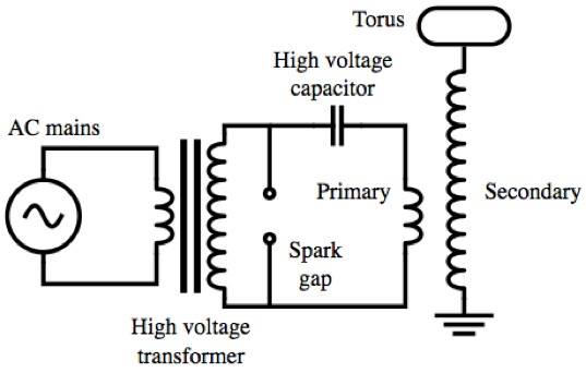
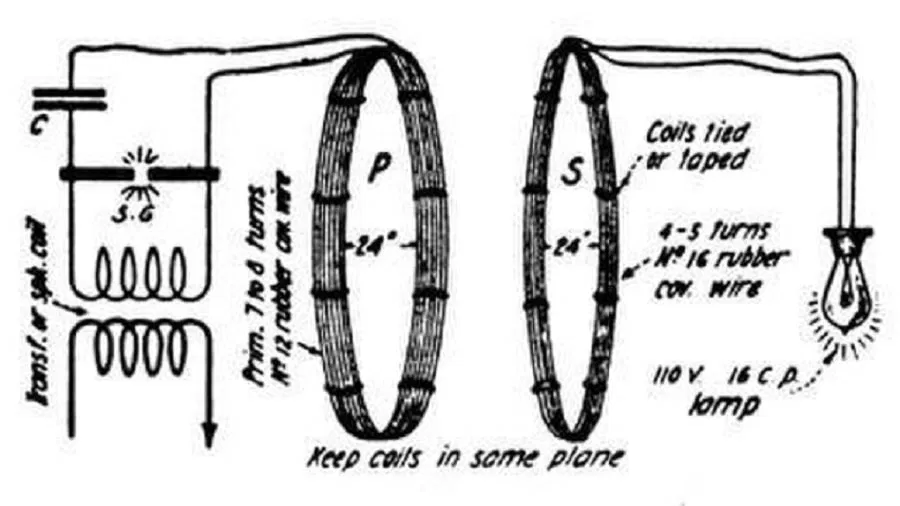
Above: The classic Tesla Coil circuit diagram. The secondary is in the T1 configuration.
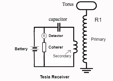
Typical low-power Tesla wireless communications receiver circuit using a coherer. The primary coil above is the secondary coil in the T1 configuration, making this an R1 type receiver. Tesla spent time developing this exact receiver technology using the Colorado Springs coils. The detectors used were of various types: small incandescent bulbs, telegraph sounders, small stepper motors, current meters with a moving needle or dial, relays... In some circuits the detector was replaced with a coil, and the energy pulse was inductively coupled to another receiver circuit. Then two or more receiver elements have to work together for an output device to function.
A way to turn a Tesla transmitter circuit into a communication receiver: the high-voltage power supply is switched out, usually for a battery of low voltage, and the spark gap or circuit controller switch, if used, gets replaced with a coherer or sometimes a rotational receiver can be applied. The energy to trigger the coherer, or charge the capacitor, is picked up by the grounded coil, R1, which resonates at a specific tuned frequency produced by the transmitter, causing current to flow through the coil R1. The energy of this resonating current is induced electromagnetically into the receiver "tank" or oscillating circuit shown in diagram. See US Patents: 645,576 -and- 649,621: - The "working devices" shown in the patents are lamps and motors being powered by the transmitter, but Tesla stated that before lamps and motors could be applied you had to be able to use sensitive devices: coherers and rotational receivers. These devices inevitably work best when coupled to a significant value of capacitance, and a coil. As the power levels in the transmitter were developed, or if the receiver was located close to the transmitter: first the battery can be dispensed with, then the coherer can be removed. At very high energy levels, even rotational commutators are no longer required. All you need is a grounded, tuned, circuit for the output device: like a motor with a tuned field and armature: The motor field serves as the inductance, the coil. Then you add capacitance and tune the coil to the frequency of your motor for example.
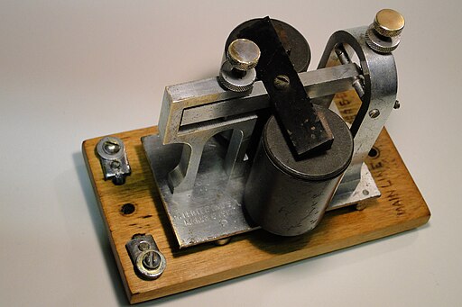
Above: Common telegraph sounder of the type Tesla often used as a detector or translating device "R" in his receiver circuits.
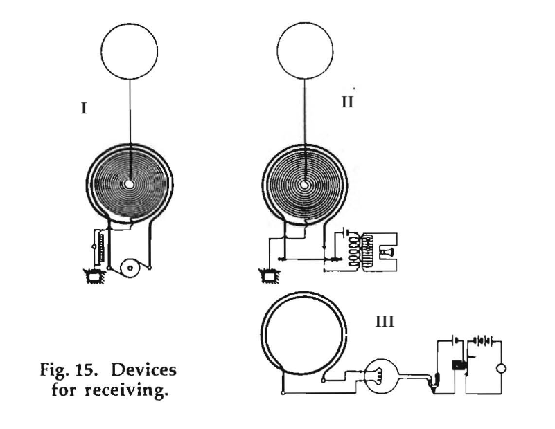
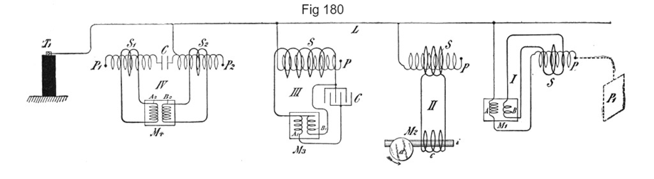
"This [Fig. 15, Diag. III] is another [drawing of a] device which I also used with success, but not telephonic. It operated on the principle of the Reis air thermometer ... [I]n the bulb is a resistance wire which is heated and cooled, owing to the fluctuations of the received currents. The attendant expansions and contractions of the air operate a little mercury column, pushing it back and forth. Curiously enough, for receiving telegraphic signals, this crude instrument was certainly good, but of course it was not suited for telephonic reception." - N. Tesla, 1897 Lecture.
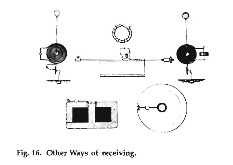
"I [have] several magnets of various forms, like this [Fig. 16, center], and employed a cord in the field, which, when the current traversed it, vibrated and established a contact. Or, I [use] a small coil... through which the current was passed, and which by its vibrations produced the signal, an audible note, or anything else ... [I]n my writings ... I had already shown the reaction of the high frequency and low frequency currents on magnetic fields, and had specified the frequencies within which one has to keep in order to receive efficiently audible notes." - N. Tesla, 1897 Lecture.
Above: Tesla designed vibrating wire receiver used between 1896 - 1899. This is a cross between a musical instrument and an electromagnetic device. The working parts are diagramed in Fig. 15 and Fig. 16 above. The function is fairly simple: the receiver circuit output is directed across a wire under tension, just like in a stringed musical instrument. In order to work best, this wire under tension must be tuned mechanically, like a stringed instrument, to the frequency of the transmitter. This frequency is an audible note, because this system works with audio frequency energy. Once the wire is connected, put under tension, and tuned to the required frequency: it is then surrounded by a powerful magnetic field produced typically with a battery powered electromagnet. When current of the same frequency is picked up by the grounded receiver coil it is passed inductively into the short secondary, passes through the wire under tension, causing it to vibrate audibly, like a musical instrument.
Tesla developed high-energy harmonic oscillators that he was applying as a transmitter. This meant there were multiple channels being transmitted simultaneously.
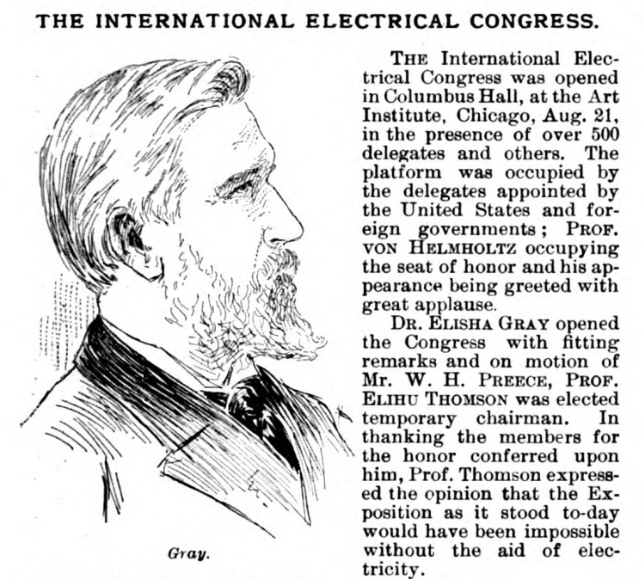
Tesla was good friends with, and very familiar with the work of, Dr. Elisha Gray. Tesla considered Gray to be the true inventor of the telephone, and Gray's work with harmonic networks on telegraph lines was going to be developed into a multichannel digital control system on Tesla's wireless system. The system would transmit voice, ticker tape feeds with stock trades, facsimile, even remote control precision devices like telautographs.
Tesla talked about remote control robots as receivers.
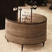
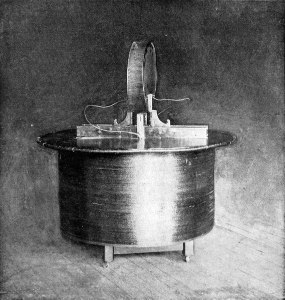
Receiving Table for Tesla Wireless. See: Nikola Tesla Transmitters -&- Oscillators.
Martin wrote about this technology in Century Magazine, April, 1895.
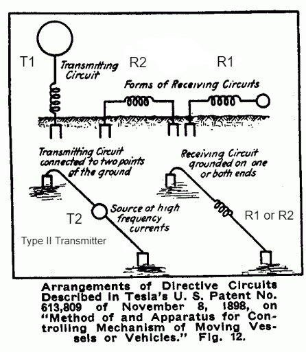
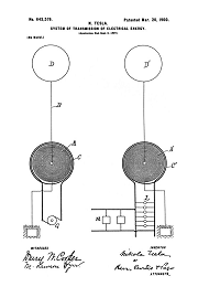
This work was begun seriously in late 1889 and early 1890, I believe, and a great deal of research was performed early using spark-gap excited high-frequency oscillators discharging Leyden jars before U.S. Patents 462,418 -and- 454,622 were filed in early 1891. In the lab, all the demonstration models operated with strictly inductive coupling between the transmitter and receiver coil as shown above. In a commerical transmitter configuration the transmitter and receiver coils would both be grounded, and the air terminals connected to capacitance, and then energy would flow between coils through the ground connection. However, large coil inductors were patented for control purposes in U.S. Patent 613,809 so the above diagram does in fact count as a Tesla patented transmitter and receiver, exactly as shown.
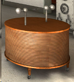
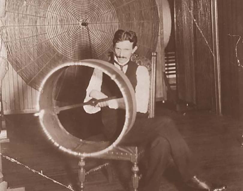
You will have to excuse the poor quality images, photos of this stuff are rare. There is a reproduction image on this page mixed in with images scanned from magazines and recovered photos. This first section is nothing special, basically a hollow wooden or fiberboard drum wound with a single layer of insulated wire, mounted on a wheeled platform, with a table top. A subscriber to Tesla's system would have one or more of these in their home. The top was removable and inside there were one or more capacitors, and taps taken off the drum coils. When adjusted with the correct amount of inductance and capacitance the table would literally resonate when matched to the transmitter frequency. Tesla planned to apply several different length coils in each receiver, so that only a combination of received frequencies would activate a specific output device.
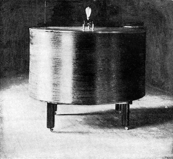
The bulb illuminated above is a standard 16 candlepower Sawyer-Man stopper type lamp. The company that made these bulbs sucessfully defended patent infringement cases filed by General Electric, so Westinghouse purchased the company and manufactured the bulbs for 20 years until the Edison and General Electric patents expired. These bulbs were used at the 1893 World's Fair by the tens of thousands.
When the Master Oscillator in the lab was energized, the receiving coil wound on the drum would pick up enough energy through induction to light bulbs.
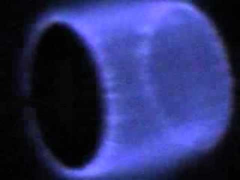
When the ends of the coil were terminated with metal disks placed two inches apart, and the transmitter energized, the space between would fill with corona and sparks. When the frequency was low enough, motors could be operated wirelessly, without using the receiver table. At higher frequencies you could light bulbs, operate rotational receivers, and coherer type receivers. Tesla stated that he invented conjoint action to prevent sensitive detectors from burning out in the field produced by the transmitter.
All Tesla power transmitters are descended from the circuit Tesla demonstrated in lecture in 1891 and made it into the Martin Book as Figure 125. Tesla's transmitter can be configured multiple ways. In the laboratory these transmitters were configured to produce a very powerful inductive field, a higher frequency version of the field produced by Tesla's Egg of Columbus. With the transmitter circuit operating, a simple coil of wire wound up to the right size would "couple" to the transmitter inductively and you could pull 3/4 of a horsepower from the transmitter and use it to light bulbs, run high-frequency motors, etc.. The transmitter was so powerful that sensitive technology like coherers and even rotational receivers could not be used at the main oscillator frequency. In the lab Tesla mostly worked on transmitter development. But he spent time on developing the lamps to be used, and small wireless high-frequency synchronous motors to be used to rotate clockwork for rotational receivers, rotating coherers, ticker tapes drives, and of course clocks.
See Tesla's Lecture before the Franklin Institute 1893
In the Tesla system that was nearly completed at Wardenclyffe, the carrier wave would operate the motor with a ground connection, and a substantial capacitance on the open end; or with the R2 two-terminals grounded receiver configuration. The transmitter produces a broad band of harmonic frequencies. These higher frequency harmonics are much lower in power than the carrier wave, but each harmonic acts as a separate communication channel. Each channel or harmonic would have their own circuits inside the receiving table, and these circuits would respond to modulation performed at the transmitter. As a Tesla system subscriber your receiving table could light a reading lamp, and operate a ticker tape and/or a Morse code type telegraph sounder. You could only receive, and you would only receive messages if you subscribed. The plan was to use wired telegraph from the stock market floor to the transmitter station, then the stock trades would be converted and transmitted out as a combination of harmonic frequency modulations. The receiving table would convert them back to telegraph sounder or ticker tape machine. The carrier wave from the transmitter would provide the energy to turn the small synchronous motor, you might have to use a hand crank to get it started, but once running it would rotate coherers and rotational receivers, pull a ticker tape, run a clock... The sensitive devices (coherers, rotational receivers, etc.) would be in circuits tuned to the correct combination of higher frequency harmonics to operate the output devices.
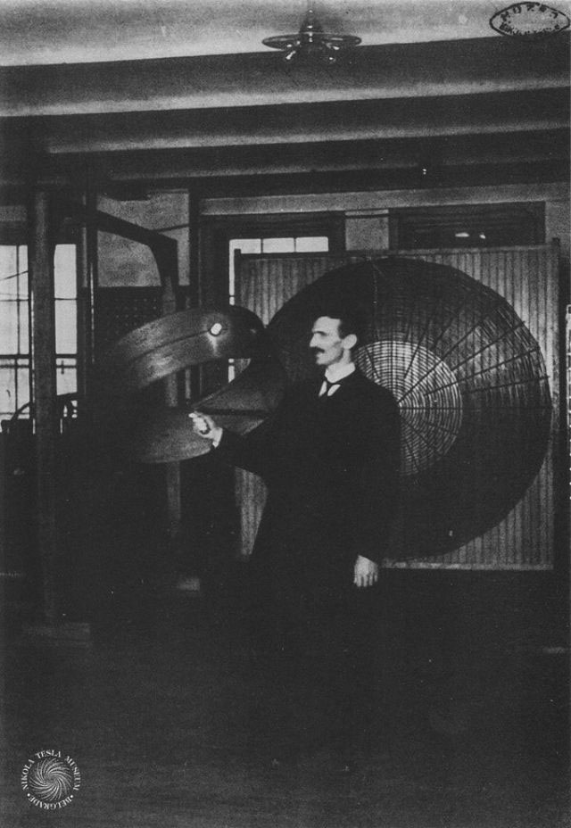
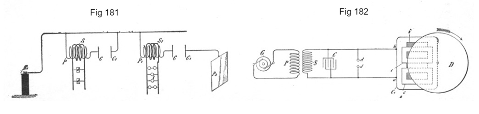
Above: Conjoint action. The cardboard drum is wound with three separate coils, all of differing length, one with a light bulb in series. Only when both coils without bulbs were energized at their specific frequencies, would the third coil containing the bulb produce any current. This development led the way to wireless multiplexing and modern computer logic gate technology:
US Patents 723,188 -and- 725,605
"Broadly stated, this invention consists in generating two or more kinds or classes of disturbances or impulses of distinctive character with respect to their effect upon a receiving-circuit and operating thereby a distant receiver which comprises two or more circuits, each of which is tuned to respond exclusively to the disturbances or impulses of one kind or class and so arranged that the operation of the receiver is dependent upon their conjoint or resultant action." - N. Tesla - US Patent 723,188
Q. Can you describe any other forms of receiver which you used in practicing this invention prior to your Colorado trip?
A. Yes, sir; I can describe a number of such instruments I used. One in particular, of which I have already spoken, I believe. This was a coil wound around a cylinder of large diameter covered on top with a board so that it resembled a table on which I often placed the apparatus for receiving. Within this coil was another coil, and the terminals of both were led to the board so as to be readily accessible. I very frequently used this apparatus in the following way: I would pass through the cable laid around the room two electrical oscillations of different periods and would tune one of the coils mentioned to one of the oscillations, and the other to the other oscillation. I used frequently condensers and inductances for this purpose. As stated before, this apparatus was very convenient to use because I was familiar with the vibrations, the constants of the circuits, and all other particulars, and could complete the test in a very short time. To give an idea I may mention the article in the Century of April, 1895, by T. C. Martin, in which such an instrument is shown in Figures 9 and 10. This apparatus illustrated in the Century article was, however, destroyed by fire, but in my laboratory in Houston Street I constructed a similar one, which I have frequently used as stated. Besides this, I had a great many other apparata of this kind which I frequently employed in my demonstrations or lectures with tuned circuits. I may mention, for instance, a coil which was provided with a handle to which one of its ends was attached, the other end being connected to a loop of rather thick aluminum wire, which served as capacity terminal. On the lower end of the coil, near the handle, was wound another coil of few turns of wire, to which I often connected a small condenser, adjusting its capacity so that the coil was powerfully excited when a certain vibration was passed through the cable around the room, the other coil responding to another vibration, properly chosen, so that both vibrations would not greatly interfere with each other. It was a common experiment with me to take a hoop of wire closed through a minute lamp and light the latter by the conjoint action of the two coils. In fact, I was compelled to adopt this expedient because frequently in my demonstrations, when I showed my experiments to an audience, it would happen that when I wanted to operate single circuits with some devices more than one circuit would respond, and people would call my attention to this, and I would then have to say that the circuits were not carefully tuned. But, by adopting two vibrations through the cable around the room I could always manage to operate one single device out of a great many. Besides this coil, which I frequently used, I had probably a dozen of others, similarly constructed and adjusted, which I showed on many occasions.
- Nikola Tesla - New York, August 5, 1902
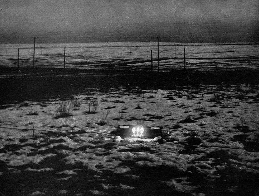
An Alley photograph from Colorado Springs documenting three lights receiving power by means of electrodynamic induction from an oscillator 60 feet (18 m) from the bulbs (placed on the ground outside the building to demonstrate they had no connection to the power source). Wiki
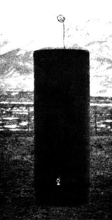
Another Alley photo of a grounded tuned coil in resonance with a transmitter, illuminating a light near the bottom of the picture. Tesla did not disclose how far away the transmitter was. Wiki
See: Cymatics
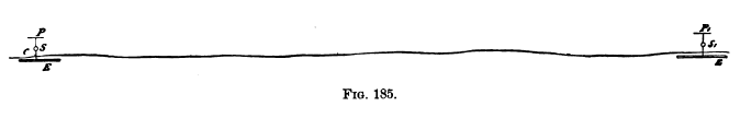
The global system depended on conductive coupling, rather than inductive coupling, and Tesla introduced the transmitter and receiver geometry in Figure 185 during the lecture given before the Franklin Institute in 1893.
In the lab, most Tesla receivers were inductively coupled, no grounds were used in the transmitter or in the receiver. All of the energy picked up by the receivers came from a high-frequency (over 2000 Hz) rotating magnetic field, but this has no range. Once you left the laboratory building the inductive coupling failed due to range restrictions. In order to use both the transmitter and the receiver technology at any significant distance, both the transmitter and receiver circuits must be well grounded to the Earth, as shown in the diagram at the top of the page.
In the lab, all of Tesla's wireless power development was performed using extremely range limited inductive coupling, but the inductive fields he produced were both extremely powerful and extremely reliable. Tesla was well aware that transitioning the technology for global application required new and more powerful (and expensive) transmitter designs: but the receivers were already proven reliable technology in the lab. The only changes required to make the inductive receivers work remotely in a global system was to ground the receiver and provide the circuit with a sufficient top capacitance to permit efficient current flow through the receiver coil. An alternate solution is to run insulated wire a fractional wave length of the transmitter to well grounded terminals connected to the Earth as shown as R2 in Fig 12 top.
ROTATIONAL RECEPTION OF ISOCHRONOUS WAVES
Angular Displacement Receivers
Tesla's Coherer Technology
Wireless Communications Receivers
Tesla Transmitters
Wireless Transmission of Electrical Energy
To the Archive Page Discussion on Tesla's Technology